yashica 124g manual

Yashica Mat 124G: A Comprehensive Guide

This guide delves into the Yashica Mat 124G, offering resources like service manuals and exploded diagrams readily available online for download, aiding in camera repair.

PDF manuals, including the Yashica Mat 124G Camera Manual, are accessible, with some sites requesting a small fee for file access, ensuring continued online availability.

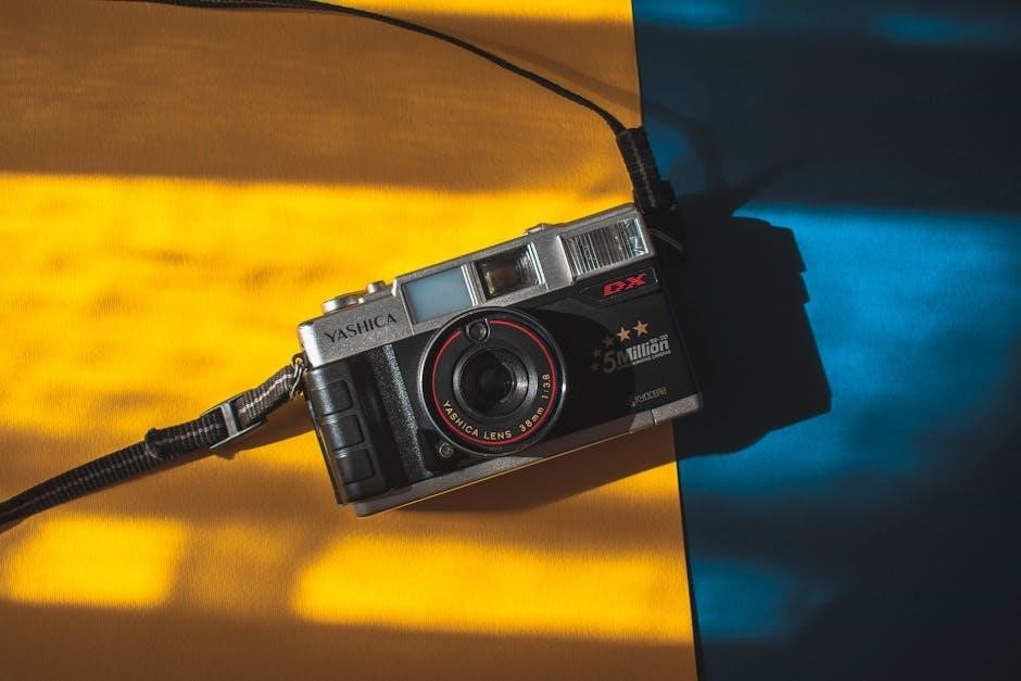
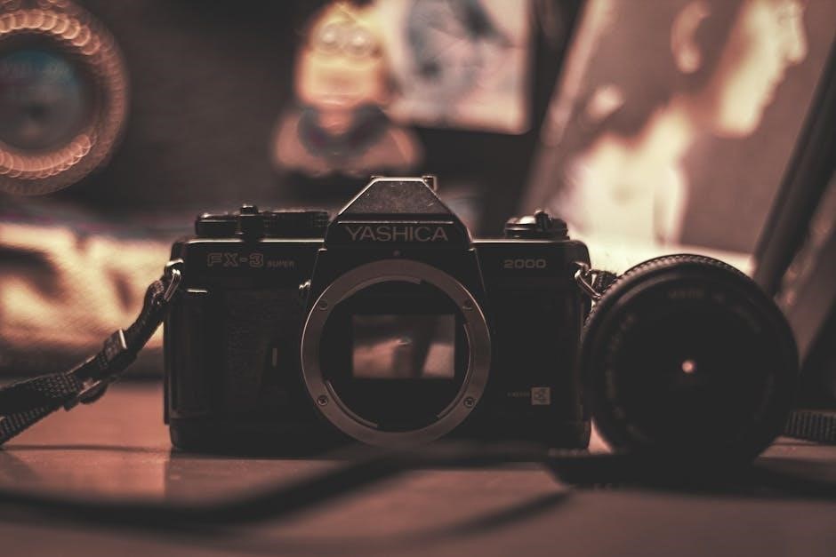
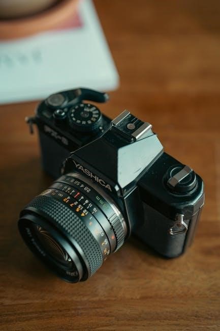
The Yashica Mat 124G stands as a celebrated Twin Lens Reflex (TLR) camera, renowned for its exceptional image quality and robust build. Introduced in 1970, it quickly gained popularity among photography enthusiasts, offering a compelling alternative to more expensive TLR options. A key aspect of owning and maintaining this classic camera is access to comprehensive documentation, and thankfully, a wealth of resources exists;

Yashica Mat 124G manuals, including detailed service manuals, are readily available online. These manuals aren’t just user guides; they are essential tools for understanding the camera’s intricate mechanics, facilitating repairs, and ensuring optimal performance. You can find these resources in PDF format, offering detailed schematics and step-by-step instructions.

The availability of exploded diagrams is particularly valuable for those undertaking repairs, allowing for easy identification of parts and their correct placement. Websites dedicated to camera repair often host these manuals, sometimes requiring a small contribution to support their services. Understanding the camera’s features is greatly enhanced by studying these readily accessible documents.

Historical Context and Significance

The Yashica Mat 124G emerged during a pivotal era in camera development, the early 1970s, when TLR cameras were still highly sought after for their unique shooting experience and image quality. Yashica strategically positioned the 124G as a more affordable, yet capable, alternative to established brands like Rolleiflex, democratizing access to TLR photography.

The camera’s significance is further underscored by the enduring availability of its manuals and repair documentation. The fact that detailed service manuals and exploded diagrams remain accessible decades later speaks to the camera’s lasting appeal and the dedication of the photographic community.

These manuals aren’t merely historical artifacts; they represent a commitment to keeping these cameras functioning for generations. The ease with which one can now find Yashica Mat 124G manuals online demonstrates the camera’s continued relevance and the desire to preserve its legacy, ensuring its place in photographic history.

Understanding the Camera’s Features

Yashica Mat 124G manuals detail its Twin Lens Reflex system, lens specifications, shutter mechanics, and aperture controls, crucial for mastering this classic camera.

Twin Lens Reflex (TLR) System Explained

The Yashica Mat 124G employs a Twin Lens Reflex (TLR) system, a distinctive photographic approach. This means the camera features two identical lenses mounted side-by-side – one for viewing and one for taking the photograph. Light enters both lenses, but only the taking lens exposes the film.

Looking through the viewing lens, you see a direct, real-time image on the focusing screen, unaffected by the taking lens’s settings. This allows for precise composition and focusing. However, it’s crucial to understand that the viewing image is reversed left-to-right, requiring mental adjustment during framing.

Manuals emphasize the importance of parallax correction, especially for close-up shots, as the viewing and taking lenses aren’t perfectly aligned. This misalignment causes a slight difference in the captured image’s perspective. Understanding this system, as detailed in the Yashica Mat 124G documentation, is key to achieving sharp, well-composed photographs with this iconic camera.

Key Specifications: Lens, Shutter, and Aperture

The Yashica Mat 124G boasts a high-quality 80mm f/3.5 Yashinon lens, renowned for its sharpness and contrast. This lens is fixed, meaning it cannot be removed or interchanged. The camera utilizes a Copal leaf shutter, offering speeds ranging from 1 second to 1/500th of a second, plus Bulb mode for extended exposures.

Aperture control is managed via a ring on the taking lens, with settings from f/3.5 to f/22. Manuals detail how these settings interact to control depth of field and light entering the camera. The aperture ring is coupled to an exposure meter, though its accuracy should be verified with a separate light meter.

Understanding these specifications, as outlined in the Yashica Mat 124G documentation, is fundamental to mastering the camera’s capabilities and achieving desired photographic results. Precise control over these elements is crucial for successful image creation.

Metering System: How it Works (and its limitations)

The Yashica Mat 124G features a selenium-based light meter, integrated into the camera body. This meter measures light levels and provides exposure suggestions via a needle indicator in the viewfinder. The meter operates without batteries, deriving power directly from ambient light. However, it’s crucial to understand its limitations.

Manuals emphasize that selenium meters degrade over time, leading to inaccurate readings. Gold-plated contacts in the ‘G’ model are intended to improve conductivity, but don’t prevent aging. Readings can be affected by extreme temperatures and low light conditions.

Therefore, relying solely on the built-in meter is not recommended. Cross-referencing with a handheld light meter or utilizing the Sunny 16 rule is advisable for accurate exposure. Regular meter checks and awareness of its potential inaccuracies are essential for consistent results.

Operating the Yashica Mat 124G

Manuals detail film loading, exposure settings, focusing, and the self-timer. Proper operation ensures optimal image quality from this classic Twin Lens Reflex camera.

Loading and Unloading Film

Loading film into the Yashica Mat 124G requires a specific sequence, detailed in the camera’s manual. First, open the back cover using the latch. Then, insert the 120 film spool into the left-side film chamber, ensuring it clicks into place.

Next, draw the film leader across the film gate and engage it with the take-up spool on the right side; Advance the film using the winding knob, observing the film counter to confirm proper advancement.

Unloading film is equally straightforward. After completing the roll, rewind the film back onto the supply spool using the rewind crank. Once fully rewound, open the back cover and carefully remove the film. The manual emphasizes gentle handling to avoid light leaks and damage to the film.

Always perform these steps in subdued light to prevent accidental exposure of unexposed film. Refer to the Yashica Mat 124G Camera Manual for detailed diagrams and illustrations.

Setting Exposure: Aperture and Shutter Speed

Setting exposure on the Yashica Mat 124G involves coordinating aperture and shutter speed, as detailed in the manual. The aperture ring, located on the taking lens, controls the lens opening, influencing depth of field and light intake. Lower f-numbers (e.g., f/2;8) create shallow depth of field and allow more light, while higher f-numbers (e.g., f/16) increase depth of field and reduce light;

The shutter speed dial, situated around the taking lens, determines the duration of light exposure. Faster shutter speeds (e.g., 1/250s) freeze motion, while slower speeds (e.g., 1/30s) allow more light but can introduce motion blur.

The manual explains using the built-in meter (though with limitations) as a guide, but experienced users often employ external light meters or the sunny 16 rule for accurate exposure. Proper coordination of these settings is crucial for well-exposed images.

Focusing Techniques for Sharp Images

Achieving sharp focus with the Yashica Mat 124G relies on mastering its twin-lens reflex (TLR) focusing system, as outlined in the camera manual. Viewing is done through the sports finder, while the taking lens focuses independently. Rotate the focusing knob on the camera’s side until your subject appears sharp in the viewfinder.

Due to parallax error – the difference between what the viewing lens sees and what the taking lens captures – the manual advises compensating, especially at closer distances. Parallax markings are present on the focusing screen to aid in this correction.

Precise focusing requires patience and practice. Utilizing a focusing cloth and carefully observing the image in the viewfinder are key. Remember that depth of field, controlled by the aperture, also influences sharpness.

Using the Self-Timer

The Yashica Mat 124G features a simple yet effective self-timer mechanism, detailed within the camera manual. Located on the front of the camera, the self-timer lever initiates a delay before the shutter releases, allowing you to include yourself in photographs.

To activate, gently push the self-timer lever downwards until it clicks into place. This sets the timer; The shutter button then becomes inactive; pressing it will not immediately take a picture. The manual indicates a delay of approximately 5-10 seconds before the shutter fires.

During the delay, the self-timer mechanism is visible, counting down the seconds. Ensure you are positioned and ready before activating the self-timer. Once the timer completes, the shutter will release automatically. Remember to return the lever to its original position after use.

Maintenance and Repair

Yashica Mat 124G upkeep involves cleaning, storage, and addressing common issues using service manuals and exploded diagrams for successful camera repair.

Cleaning and Storage Best Practices

Maintaining your Yashica Mat 124G requires gentle cleaning practices to preserve its functionality and appearance. Regularly use a soft brush to remove dust from the lens elements and camera body, avoiding abrasive cleaners or liquids directly on the lens. A blower can effectively dislodge particles without causing scratches.

For the body, a slightly damp, lint-free cloth is sufficient. Pay attention to the film compartments, ensuring they are free of debris. When storing the camera, choose a cool, dry place away from direct sunlight and extreme temperatures. A camera bag or case provides excellent protection against dust, moisture, and accidental impacts.

Consider using silica gel packets within the storage container to absorb any residual moisture. Avoid long-term storage with batteries installed, as leakage can cause corrosion. Proper cleaning and storage significantly extend the lifespan of your Yashica Mat 124G, ensuring years of reliable photographic enjoyment.

Common Issues and Troubleshooting

Yashica Mat 124G cameras, while robust, can experience certain issues. A frequent problem is light seal deterioration, causing light leaks onto film – easily addressed with replacement kits. Sticky shutter speeds often result from aged lubricants; a camera repair specialist is recommended for this. Dim viewing screens can hinder focusing, sometimes improved with careful cleaning, but often indicate screen degradation.

If the film advance mechanism feels stiff, avoid forcing it; internal lubrication may be needed. Meter inaccuracies can occur, requiring calibration or reliance on an external light meter. Before attempting any repairs, consult the service manual for detailed instructions and exploded diagrams.

Remember, improper disassembly can cause further damage. Online forums and communities offer valuable troubleshooting advice from experienced users. When in doubt, seeking professional repair is the safest course of action to preserve your camera’s functionality.

Finding and Utilizing Service Manuals & Exploded Diagrams

Yashica Mat 124G repair relies heavily on accessible documentation. Numerous online resources host service manuals and exploded diagrams. Websites dedicated to camera repair frequently offer downloadable PDFs, sometimes for a small fee to support site maintenance. The central-manuals-camera archive provides a direct link to the Yashica Mat 124G repair manual in PDF format.

Exploded diagrams are invaluable for understanding the camera’s internal structure during disassembly and reassembly. These diagrams clearly illustrate component placement and relationships. When utilizing these resources, pay close attention to part numbers and revision levels.

The Internet Archive also hosts digitized versions of these manuals. Always cross-reference information from multiple sources to ensure accuracy. Careful study of these documents is crucial before attempting any repairs, minimizing the risk of damage.

Replacing Light Seals

Light seals in the Yashica Mat 124G inevitably degrade over time, causing light leaks onto film. Replacing them is a common repair. Kits specifically for the Yashica Mat 124G, including foam replacements, are readily available from various online retailers, such as USCamera. These kits typically include seals for the back door, film compartments, and viewing/taking lens areas.

Careful disassembly, guided by the service manual and exploded diagrams, is essential. Gently remove the old, deteriorated foam, ensuring no remnants remain. Clean the sealing surfaces thoroughly before applying the new adhesive-backed foam.

Precise placement is critical to prevent future light leaks. Take your time and refer to images of a properly sealed camera. A successful seal replacement restores image quality and preserves the camera’s functionality.

Resources and Further Learning

Online communities and forums offer valuable Yashica Mat 124G support, while PDF manuals and repair guides enhance understanding and maintenance skills.

Online Communities and Forums

Engaging with online communities dedicated to film photography, and specifically the Yashica Mat 124G, proves invaluable for owners seeking assistance, sharing experiences, and troubleshooting issues. Numerous forums host dedicated threads where users discuss everything from manual interpretation to intricate repair procedures.

The Learn Camera Repair Facebook Group is a particularly active resource, offering tutorials and direct access to experienced technicians. These platforms often contain user-submitted service manuals, exploded diagrams, and practical advice not readily found elsewhere.

Members frequently share insights on sourcing parts, performing light seal replacements, and resolving common mechanical problems. Don’t hesitate to search existing posts or create new ones detailing your specific challenges; the collective knowledge of these communities can significantly simplify Yashica Mat 124G ownership and maintenance.

Recommended Books and Articles

While dedicated books solely focused on the Yashica Mat 124G are scarce, resources covering Twin Lens Reflex (TLR) photography generally provide valuable context and operational understanding. Exploring broader guides on medium format film cameras will enhance your grasp of the 124G’s mechanics and photographic principles.

Online articles and reviews frequently dissect the camera’s features, offering practical tips for achieving optimal results. Searching for “Yashica Mat 124G review” or “TLR photography guide” yields a wealth of information.

Furthermore, examining articles detailing repair and maintenance, even those for similar TLR models, can prove beneficial. Remember to supplement these resources with the official manual, readily available as a PDF download, to fully comprehend the camera’s functionalities and ensure proper operation and care.

Where to Purchase Parts and Accessories

Sourcing parts for the Yashica Mat 124G often involves online marketplaces specializing in vintage camera components. Websites like eBay frequently list Yashica parts, including light seals, focusing screens, and even complete camera bodies for spares. Dedicated camera repair shops may also stock or be able to order specific components.

USCamera is a noted supplier of foam seals specifically for all Yashica TLR cameras, including the 124G, crucial for preventing light leaks. When seeking parts, referencing the exploded diagram from the service manual is invaluable for identifying the correct component.

Be mindful of shipping costs and seller reputation when purchasing online. Occasionally, repair specialists offer refurbished parts or complete repair services, providing a convenient alternative to DIY fixes. Always verify compatibility before purchasing.

Yashica Mat 124G vs. Other TLR Cameras

Compared to contemporaries, the Yashica Mat 124G distinguishes itself with a robust build quality and a relatively bright lens, offering excellent image sharpness for a medium format TLR. While many TLRs share similar optical principles, the 124G’s metering system, though selenium-based and prone to inaccuracy over time, provides a convenient exposure guide.

Unlike some earlier Yashica models, the ‘G’ variant features gold-plated meter contacts, improving reliability. Compared to the Mamiya C series, the 124G is generally more compact and lighter, making it easier to handle. However, Mamiya offers interchangeable lenses.

The Yashica Mat 124G often represents a more affordable entry point into TLR photography than brands like Rolleiflex, while still delivering comparable image quality when properly maintained, as detailed in available manuals and repair guides.

craftsman 1900 psi pressure washer manual

Craftsman 1900 PSI Pressure Washer Manual: A Comprehensive Guide

This manual details the Craftsman 1900 PSI pressure washer, offering parts lists, diagrams, and repair guidance,
including engine specifics and troubleshooting for optimal performance and longevity of your cleaning equipment.

The Craftsman 1900 PSI Pressure Washer is a versatile cleaning tool designed for a wide range of outdoor tasks, from washing vehicles and siding to cleaning decks and patios. This manual serves as a comprehensive resource for owners, providing detailed instructions on safe operation, routine maintenance, and effective troubleshooting. Understanding your pressure washer’s components and capabilities is crucial for maximizing its performance and ensuring its longevity.

Whether you’re a homeowner tackling seasonal cleaning or require a reliable tool for more demanding projects, this guide will equip you with the knowledge to operate and maintain your Craftsman 1900 PSI model efficiently. We’ll cover everything from initial setup and safety precautions to identifying and resolving common issues, referencing available parts lists and diagrams for simplified repairs.

Understanding Pressure Washer Basics

Pressure washers utilize high-pressure water spray to remove dirt, grime, and debris from surfaces. The core components include a pump, which generates the pressure; an engine or motor to power the pump; a hose to deliver water; and a wand with interchangeable nozzles to control the spray pattern. PSI (pounds per square inch) measures the water pressure, with 1900 PSI being suitable for medium-duty cleaning tasks.

GPM (gallons per minute) indicates the water flow rate, impacting cleaning efficiency. Understanding these basic principles allows for optimal nozzle selection and effective cleaning. Different nozzles create varying spray angles – from wide-angle for gentle cleaning to narrow-angle for concentrated power. Proper technique and nozzle choice prevent damage to surfaces and maximize cleaning results.

Safety Precautions & Operating Instructions

Always wear safety glasses and appropriate clothing; never point the wand at people or animals, and disconnect the power source when not in use.

General Safety Rules

Prioritize safety when operating your Craftsman 1900 PSI pressure washer. Always read and understand this manual before use. Wear safety glasses to protect your eyes from debris. Avoid directing the spray at yourself, others, or animals.

Ensure a stable footing during operation and never overreach. Disconnect the power source (or engine) before performing any maintenance or changing accessories. Do not modify the pressure washer in any way.

Be aware of your surroundings and potential hazards. Keep children and pets away from the work area. Never use flammable liquids or solvents in the pressure washer. Inspect the hose for damage before each use.

High-pressure spray can cause serious injury; exercise extreme caution. Avoid spraying electrical components. If using an extension cord, ensure it is rated for outdoor use and the correct amperage.

Pre-Operation Checklist

Before each use of your Craftsman 1900 PSI pressure washer, a thorough checklist is crucial. First, verify the power source is properly grounded and matches the unit’s requirements. Inspect the high-pressure hose for cracks, kinks, or leaks – replace if damaged.

Check the water supply connection, ensuring it’s secure and provides adequate water flow. Confirm the nozzle is correctly installed and appropriate for the cleaning task. Examine all fittings and connections for tightness.

Ensure the detergent tank (if used) is clean and filled with the correct detergent. Verify the trigger mechanism operates smoothly. Finally, clear the work area of any obstructions and ensure bystanders are a safe distance away.

A quick pre-operation check minimizes risks and maximizes the efficiency of your cleaning process.

Starting and Stopping the Pressure Washer

To start your Craftsman 1900 PSI pressure washer, first, ensure all connections are secure and the water supply is fully on. Turn the power switch to the “ON” position. If equipped, prime the pump by pressing the unloader valve trigger until water flows consistently.

Pull the starter cord firmly and steadily – avoid rapid pulls. Once running, gradually increase the throttle if applicable. To stop, release the trigger, turn the power switch to “OFF”, and disconnect the water supply.

Never leave the pressure washer unattended while running. Allow the engine to cool down before storing. Proper starting and stopping procedures extend the life of your equipment and ensure safe operation.

Always refer to the specific model’s instructions for detailed guidance.

Proper Nozzle Selection

Selecting the correct nozzle is crucial for effective and safe cleaning with your Craftsman 1900 PSI pressure washer. Different nozzles deliver varying spray patterns and intensities. A 0-degree nozzle provides a concentrated stream for stubborn dirt, but use with extreme caution as it can damage surfaces.

A 15-degree nozzle is suitable for heavy-duty cleaning, while 25-degree and 40-degree nozzles are ideal for general-purpose tasks. The soap nozzle delivers detergent at a lower pressure.

Always test the nozzle on an inconspicuous area first. Avoid using high-pressure nozzles on delicate surfaces like painted wood or vehicles. Regularly inspect nozzles for clogs and replace them when necessary to maintain optimal performance.

Components and Parts Identification

Detailed diagrams showcase the pressure washer’s assembly, including the pump, engine (if applicable), hose, wand, and nozzles,
facilitating easy part location and maintenance for your Craftsman 1900 PSI model.

Pressure Washer Diagram

The following diagram provides a comprehensive visual breakdown of the Craftsman 1900 PSI pressure washer’s key components. This detailed illustration identifies each part, from the high-pressure pump and electric motor (or gasoline engine) to the trigger gun assembly, spray wand, and various hose connections.

Numbered callouts correspond to a detailed parts list (see section 6), enabling precise identification for maintenance, repair, or replacement. Pay close attention to the unloader valve, crucial for pressure regulation, and the detergent injection system.

The diagram also highlights safety features, such as the thermal relief valve and high-pressure hose, emphasizing their importance. Understanding this visual representation is fundamental for effective troubleshooting and ensuring the longevity of your pressure washing equipment. Refer to this diagram frequently during maintenance procedures.

Engine Specifications (If Applicable)

For Craftsman 1900 PSI pressure washers equipped with a gasoline engine, the following specifications are crucial for proper maintenance and operation. Typically, these models utilize a single-cylinder, air-cooled, four-stroke engine, often ranging from 196cc to 208cc in displacement.

Fuel requirements generally specify unleaded gasoline with a minimum octane rating of 87. The engine’s horsepower typically falls between 6.5 HP and 7.5 HP, influencing the washer’s overall performance. Oil capacity is usually around 15-20 ounces of SAE 30 weight oil, and regular oil changes are vital.

Ensure the engine is properly grounded and that the spark plug is in good working order. Refer to the engine manufacturer’s documentation for detailed information regarding valve clearances and carburetor adjustments. Always use genuine Craftsman replacement parts for optimal engine performance.

Pump Assembly Details

The Craftsman 1900 PSI pressure washer’s pump is a triplex plunger pump, designed for durability and efficient water delivery. This axial cam pump converts rotational motion into reciprocating motion, creating high-pressure water flow. Key components include three plungers, a swashplate, and inlet/outlet valves.

The pump housing is typically constructed from durable materials like aluminum, ensuring resistance to corrosion. Regular inspection of the pump seals and O-rings is crucial to prevent leaks and maintain pressure. The unloader valve, integrated within the pump, regulates pressure and prevents damage at higher settings.

Proper lubrication of the pump is essential; use only pump-specific oil. Disassembly should only be performed by qualified technicians, following the detailed parts breakdown for correct reassembly. Maintaining the pump ensures consistent performance and extends the lifespan of your pressure washer.

Hose and Wand Components

The high-pressure hose is a critical component, designed to withstand the 1900 PSI output of the Craftsman pressure washer. It’s typically reinforced with braided steel for durability and flexibility. Inspect the hose regularly for cracks, bulges, or abrasions before each use, replacing it immediately if damage is found.

The wand assembly includes a trigger gun, lance (wand tube), and nozzle attachments. The trigger gun controls water flow, while the lance provides reach and directs the spray. Nozzles determine spray pattern and intensity, ranging from wide-angle for gentle cleaning to pinpoint jets for stubborn grime;

Ensure all connections are secure before operation to prevent leaks and potential injury. Proper storage of the hose and wand – avoiding kinks and direct sunlight – will prolong their lifespan. Regularly cleaning the nozzle tips prevents clogging and maintains optimal spray performance.

Maintenance and Troubleshooting

Regular upkeep ensures peak performance. This section covers routine checks, cleaning procedures, and solutions for common issues like no start, low pressure, or leaks.

Routine Maintenance Schedule

To maximize the lifespan and efficiency of your Craftsman 1900 PSI pressure washer, adhere to a consistent maintenance schedule. After each use, thoroughly flush the system with clean water to remove any residual detergent or debris. Inspect the high-pressure hose for cracks, bulges, or leaks, and replace it if necessary.

Monthly, check the oil level (if applicable for gas-powered models) and replenish as needed. Clean or replace the air filter to ensure proper engine operation. Examine the nozzles for clogs and clear them with a fine wire. Annually, inspect the pump for wear and tear, and consider replacing seals or O-rings.

Furthermore, a seasonal inspection before storage is crucial. Drain all water from the pump and hose to prevent freezing damage. Store the unit in a clean, dry environment, protected from the elements. Following this schedule will help maintain optimal performance and prevent costly repairs.

Cleaning and Storage

Proper cleaning and storage are vital for preserving your Craftsman 1900 PSI pressure washer’s functionality. After each use, disconnect the high-pressure hose and wand. Rinse the exterior of the unit with a mild detergent and water, avoiding direct spray into the engine or pump. Thoroughly flush the pump and hose with clean water to remove any remaining soap or debris.

Before long-term storage, completely drain all water from the pump, hose, and wand to prevent freezing and corrosion. Apply a pump protector specifically designed for pressure washers. Store the unit in a clean, dry, and frost-free location, ideally indoors. Cover the pressure washer to protect it from dust and debris.

Regular cleaning and careful storage will significantly extend the life of your pressure washer and ensure it’s ready for use when you need it.

Troubleshooting Common Issues ⎻ No Start

If your Craftsman 1900 PSI pressure washer fails to start, several factors could be the cause; First, verify the power source – ensure the unit is properly plugged in or the engine has sufficient fuel. Check the circuit breaker or fuse if it’s an electric model. Inspect the engine’s on/off switch and the safety interlock mechanisms on the handle; they must be engaged correctly.

For gas-powered models, confirm the fuel valve is open and the fuel tank isn’t empty. Examine the spark plug for fouling or damage, and replace if necessary. A clogged air filter can also prevent starting; clean or replace it. If the engine attempts to start but doesn’t run, there might be a carburetor issue requiring professional attention.

Always consult the full manual for detailed diagrams and safety precautions before attempting any repairs.

Troubleshooting Common Issues ⎻ Low Pressure

Experiencing low pressure with your Craftsman 1900 PSI pressure washer? Several issues could contribute to this problem. First, check the nozzle – ensure it’s not clogged with debris. Try a different nozzle to rule out a faulty one. Inspect the high-pressure hose for kinks, bends, or damage; replace if necessary.

The water inlet filter can become clogged, restricting water flow. Clean this filter thoroughly. A failing pump is a common cause of low pressure; listen for unusual noises during operation. The unloader valve regulates pressure, and a malfunction here can also lead to low output.

Always disconnect the power source before inspecting or repairing any components. Refer to the manual’s diagrams for proper component locations.

Troubleshooting Common Issues ― Leaks

Discovering leaks in your Craftsman 1900 PSI pressure washer requires immediate attention. Begin by visually inspecting all hose connections – the high-pressure hose, the water inlet hose, and connections at the pump and spray gun. Tighten any loose fittings, but avoid over-tightening, which can damage them.

Check the o-rings and seals around the pump and spray gun for wear or damage; replace them if necessary. Inspect the pump itself for cracks or leaks, particularly around the oil cap. A leaking unloader valve can also cause water to escape.

Remember to disconnect the power supply before any inspection or repair. Always refer to the parts diagram in the manual to identify specific components and their corresponding replacement parts.

Detailed Parts List & Replacement

This section provides comprehensive breakdowns of pump, engine (if applicable), hose, and nozzle components, facilitating easy identification and ordering of replacement parts for your Craftsman unit.

Pump Parts Breakdown

The pump assembly is the heart of your Craftsman 1900 PSI pressure washer, responsible for generating the high-pressure water stream. This breakdown details each component, including the pump housing, piston assembly (pistons, connecting rods, and swashplate), high-pressure seals, and the water inlet/outlet fittings.

Detailed diagrams illustrate the correct orientation and placement of each part, aiding in reassembly after maintenance or repair. Common replacement parts include pistons, seals (O-rings and gaskets), and the unloader valve.

Understanding the function of each component is crucial for effective troubleshooting. For example, worn piston seals will lead to reduced pressure, while a faulty unloader valve can cause erratic spraying. Refer to the parts list for specific part numbers and ensure compatibility with your model before ordering replacements.

Engine Parts Breakdown (If Applicable)

For Craftsman 1900 PSI pressure washers equipped with a gasoline engine, this section provides a comprehensive parts breakdown. It covers essential components like the cylinder head, piston, connecting rod, crankshaft, carburetor, and recoil starter assembly. Detailed exploded views illustrate the precise arrangement of each part, simplifying repairs and maintenance.

Commonly replaced engine parts include spark plugs, air filters, fuel filters, and carburetor components. The breakdown also identifies critical seals and gaskets necessary for maintaining engine compression and preventing oil leaks; Always refer to the engine’s model number when ordering replacement parts to ensure compatibility.

Proper engine maintenance, guided by this breakdown, extends the lifespan of your pressure washer and ensures optimal performance.

Hose and Nozzle Replacements

Maintaining your Craftsman 1900 PSI pressure washer’s hose and nozzles is crucial for consistent performance. This section details replacement procedures and specifications. High-pressure hoses can develop cracks or kinks over time, leading to leaks and reduced pressure; replacement is straightforward, requiring proper connection tightening. Always ensure the hose is rated for at least 1900 PSI.

Nozzles wear out with use, affecting spray patterns. A variety of nozzle types are available – 0°, 15°, 25°, 40°, and soap – each serving a specific cleaning purpose. Replacing a nozzle involves unscrewing the old one and securely attaching the new one.

Regular inspection and timely replacement of these components prevent damage and ensure safe operation.

Filter Replacement Guide

Maintaining clean filters is paramount for the longevity and performance of your Craftsman 1900 PSI pressure washer. Two primary filters require periodic attention: the water inlet filter and the engine air filter (if gas-powered). The water inlet filter prevents debris from entering the pump, while the air filter ensures clean air reaches the engine.

To replace the water inlet filter, locate it on the water intake connection, detach, and clean or replace with a new filter of the correct size. For the engine air filter, access it via the air filter housing, remove the old filter, and install a new one, ensuring a proper seal.

Regular filter replacement prevents damage and ensures optimal operation.

Advanced Topics & Repair

Delve into the intricacies of the unloader valve, pump repair procedures, and engine basics for comprehensive maintenance,
ensuring peak performance and extending the lifespan of your Craftsman pressure washer.

Understanding the Unloader Valve

The unloader valve is a critical component within your Craftsman 1900 PSI pressure washer, responsible for regulating pressure and preventing damage to the pump and other components. Essentially, it diverts water flow when the trigger is released, bypassing the nozzle and returning it to the pump inlet. This prevents the pump from continuously building pressure against a closed nozzle, which could lead to overheating and failure.

Understanding its function is key to troubleshooting pressure issues. A malfunctioning unloader valve can cause inconsistent pressure, reduced cleaning power, or even a complete lack of pressure. Common problems include a stuck valve, worn seals, or debris obstructing the valve’s operation. Regular inspection and cleaning of the unloader valve are vital for maintaining optimal performance. Disassembly and repair should be undertaken with caution, following the detailed instructions provided in the parts breakdown section of this manual.

Pump Repair Procedures

Pump repair on your Craftsman 1900 PSI pressure washer requires careful attention to detail and a clean working environment. Begin by disconnecting the power source and relieving all water pressure. Disassembly typically involves removing the pump housing to access internal components like pistons, connecting rods, and seals. Always refer to the pump parts breakdown diagram for proper component orientation.

Inspect all parts for wear, damage, or corrosion. Replace worn seals, O-rings, and pistons as a preventative measure. Lubricate new parts with pump-specific oil before reassembly. Ensure proper torque specifications are followed when tightening bolts to avoid leaks or damage. If you lack experience, professional repair is recommended. Incorrect reassembly can lead to pump failure and potential injury. Thoroughly test the pump after repair to confirm proper operation and pressure output.

Engine Repair Basics (If Applicable)

If your Craftsman 1900 PSI pressure washer features a gasoline engine, basic repairs may be manageable with the right tools and knowledge. Always disconnect the spark plug wire before performing any engine work. Common issues include carburetor problems, fouled spark plugs, and low oil levels. Cleaning or replacing the carburetor can often resolve starting or running issues.

Inspect the spark plug for wear and replace if necessary, ensuring the correct gap is maintained. Regularly check and maintain the oil level, using the manufacturer’s recommended oil type. For more complex repairs, such as valve adjustments or piston replacements, professional service is strongly advised. Incorrect engine repair can lead to further damage and void the warranty. Always consult the engine specifications section for detailed information and torque settings.

Winterizing Your Pressure Washer

Proper winterization is crucial to prevent damage to your Craftsman 1900 PSI pressure washer during freezing temperatures. Begin by disconnecting the water supply and running the engine until all water is expelled from the pump. Then, pump a specialized pump saver solution (antifreeze) through the system to protect internal components.

Disconnect and drain the high-pressure hose, and store it in a frost-free location. If the engine utilizes gasoline, stabilize the fuel or drain the tank and carburetor to prevent fuel degradation. Remove the spark plug and add a teaspoon of engine oil into the cylinder, then slowly pull the starter cord to distribute the oil. Store the pressure washer in a dry, sheltered area, covered to protect it from dust and debris.

Resources and Support

For Craftsman 1900 PSI support, contact Craftsman directly or explore online parts retailers. Warranty details and related product information are readily available online.

Craftsman Support Contact Information

Need assistance with your Craftsman 1900 PSI pressure washer? Craftsman offers multiple avenues for support. For immediate help, visit the Craftsman website at www.craftsman.com. There, you’ll find a comprehensive FAQ section addressing common issues, downloadable manuals (including this one!), and troubleshooting guides. You can also initiate a live chat with a customer service representative during business hours.

Alternatively, you can reach Craftsman support via phone. The customer service hotline is available at 1-888-331-4565. Be prepared to have your model number readily available to expedite the process. For parts inquiries or warranty claims, a dedicated support team can be reached through the website’s contact form. Craftsman also maintains an active presence on social media platforms like Facebook and Twitter, where you can often find helpful tips and engage with other users.

Finding Replacement Parts Online

Locating replacement parts for your Craftsman 1900 PSI pressure washer is convenient online; Several retailers specialize in small engine and power tool parts. A primary source is the official Sears PartsDirect website (www.searspartsdirect.com), where you can input your model number to find a precise parts list and diagrams. Other reputable online vendors include Amazon, eBay, and dedicated small engine parts suppliers like RepairClinic and Jack’s Small Engines.

When searching, always verify the part number matches your specific model to ensure compatibility. Pay attention to detailed descriptions and customer reviews. Consider comparing prices across different vendors. Many sites offer expedited shipping options. Before ordering, review the return policy in case the part is incorrect or defective. Utilizing the parts breakdown within this manual will greatly assist in identifying the correct component.

Warranty Information

Your Craftsman 1900 PSI pressure washer is covered by a limited warranty, protecting against defects in materials and workmanship. The standard warranty period typically begins from the date of purchase. It’s crucial to retain your original purchase receipt as proof of purchase for any warranty claims. The warranty generally covers the pump, engine (if applicable), and other core components.

However, the warranty does not cover items damaged through misuse, abuse, neglect, improper maintenance, or normal wear and tear. Modifications or attempts at unauthorized repair will void the warranty. To initiate a warranty claim, contact Craftsman customer support (see ‘Craftsman Support Contact Information’). Be prepared to provide your model number, serial number, and a detailed description of the issue.

Related Craftsman Products

Craftsman offers a wide range of outdoor power equipment to complement your 1900 PSI pressure washer. Explore their selection of lawn mowers, including gas-powered, electric, and robotic models, for comprehensive lawn care. Consider a Craftsman leaf blower to quickly clear debris after pressure washing. For yard cleanup, their chainsaws and string trimmers provide powerful performance.

Additionally, Craftsman provides various hand tools and power tools suitable for home repairs and maintenance tasks related to your pressure washer, such as wrench sets and drills. Don’t forget to check out their range of storage solutions to keep your tools organized. Visit the Craftsman website or your local retailer to discover the full product line and find accessories to enhance your outdoor projects.

gree remote control manual

Gree Remote Control Manual: A Comprehensive Guide (Updated 12/16/2025)

GREE‚ the world’s largest air conditioner company‚ offers diverse HVAC solutions․ This manual guides users through GREE remote controls‚ maximizing comfort and energy efficiency with 34 years of experience․

Gree remote controls are the central interface for operating your air conditioning and HVAC systems‚ offering convenient control over temperature‚ fan speed‚ and various advanced features․ As a global leader with over 500 million users worldwide‚ Gree prioritizes user-friendly design and functionality in its remote control technology․

These remotes aren’t simply on/off switches; they unlock the full potential of Gree’s energy-efficient systems‚ allowing for customized comfort and potential rebate eligibility․ Understanding your remote’s capabilities is key to maximizing your Gree experience․ This guide will cover everything from basic operations to advanced programming‚ ensuring you can effortlessly manage your indoor climate․ Whether you have a standard split unit or a multi-zone system‚ this manual provides the information you need․

Gree as a Global Leader in HVAC

Gree Electric Appliances has established itself as the world’s largest manufacturer of residential air conditioners‚ holding a 20․6% global market share as of 2018 and maintaining the #1 position for 14 consecutive years․ This leadership stems from 34 years of dedicated innovation and a commitment to serving over 500 million users globally․

Gree’s presence extends to major international events‚ including providing comfort solutions for the 2008 Beijing Olympics and the 2010 Africa World Cup․ Beyond air conditioners‚ Gree offers a comprehensive range of home appliances‚ demonstrating its technological prowess․ This dedication to advancement translates directly into the sophisticated functionality found within their remote control systems‚ designed for optimal performance and user satisfaction․

Types of Gree Remote Controls

Gree offers a variety of remote controls tailored to its diverse HVAC systems․ These include standard infrared (IR) remotes‚ commonly used for individual split units‚ providing basic control over temperature‚ fan speed‚ and mode․ For multi-split and ducted systems‚ more advanced remotes with zone control capabilities are available‚ allowing independent adjustments for different areas․

Furthermore‚ Gree remotes are designed to be compatible with universal remotes‚ offering users flexibility․ The availability of specific remote models can vary depending on the system type and region․ Understanding your system’s remote type is crucial for utilizing its full range of features and ensuring optimal comfort and control․

Understanding the Basic Functions

Gree remote controls share core functionalities across most models․ The Power button initiates or terminates operation․ Mode selection allows switching between cooling‚ heating‚ auto‚ dry‚ and fan-only modes․ Temperature adjustment utilizes up and down arrows‚ typically displayed in Celsius or Fahrenheit․

Fan Speed control offers options like auto‚ low‚ medium‚ and high‚ influencing airflow and comfort․ These basic functions are universally accessible‚ providing immediate control over your indoor climate․ Familiarizing yourself with these controls is the first step to maximizing your Gree system’s performance and enjoying a comfortable environment․

Power and Mode Selection

Power button operation is straightforward: a single press typically turns the unit on or off․ Mode selection is crucial for desired comfort․ Cool mode lowers the temperature‚ while Heat raises it․ Auto mode intelligently adjusts based on room temperature․ Dry mode reduces humidity‚ and Fan mode circulates air without temperature change․

Selecting the appropriate mode optimizes energy usage and ensures optimal comfort․ Some Gree remotes feature an ‘Economy’ mode for enhanced energy savings․ Understanding these modes allows for precise control over your indoor environment‚ catering to specific needs and preferences․

Temperature Control

Temperature adjustment on your Gree remote is typically managed using the ‘Up’ and ‘Down’ arrow buttons․ The display shows the set temperature‚ usually in Celsius or Fahrenheit․ Increments are often in one-degree steps‚ allowing for precise control․ Some models offer a wider temperature range for both heating and cooling․

Consider your comfort level and energy efficiency when setting the temperature․ Lowering the temperature in cooling mode or raising it in heating mode can save energy․ Many Gree systems feature a ‘Comfort’ setting‚ automatically optimizing temperature for maximum comfort․

Fan Speed Adjustment

Gree remote controls provide multiple fan speed settings to customize airflow․ Typically‚ options include ‘Auto’‚ ‘Low’‚ ‘Medium’‚ and ‘High’․ ‘Auto’ mode adjusts fan speed based on the temperature difference between the setpoint and the room temperature․ Lower speeds conserve energy and reduce noise‚ ideal for quiet operation or sleep․

Higher speeds provide faster cooling or heating․ Some advanced models offer additional settings like ‘Quiet’ or ‘Turbo’ for specialized airflow needs․ Experiment with different speeds to find the optimal balance between comfort and energy savings․ Proper fan speed selection enhances your Gree system’s efficiency․

Advanced Features & Their Functions

Gree remote controls boast advanced features beyond basic operation․ Timer and Scheduling allows pre-setting on/off times for automated comfort and energy savings․ Sleep Mode gradually adjusts temperature during the night for optimal sleep conditions․ For multi-split systems‚ Multi-Zone Control enables independent temperature adjustments in different areas․

These features enhance user convenience and efficiency․ Explore your remote’s menu to discover additional options like swing control‚ filter reminders‚ and eco-modes․ Utilizing these functions maximizes your Gree system’s performance and contributes to lower energy bills‚ offering a truly customized experience․

Timer and Scheduling

Gree remote controls offer a robust Timer and Scheduling function for automated climate control․ This feature allows users to pre-set specific times for the unit to turn on or off‚ optimizing comfort and energy consumption․ You can program different settings for various days of the week‚ tailoring the schedule to your lifestyle․

Access the timer settings through the remote’s menu‚ typically indicated by a clock icon․ Set the desired start and end times‚ and select the operating mode․ This eliminates the need for manual adjustments‚ ensuring a comfortable environment while minimizing energy waste and maximizing convenience․

Sleep Mode Operation

Gree’s Sleep Mode is designed to create a comfortable sleeping environment while conserving energy․ When activated‚ this mode gently increases the temperature after the initial setpoint‚ preventing overheating or excessive cooling during the night․ This mimics the body’s natural temperature fluctuations during sleep‚ promoting better rest․

To engage Sleep Mode‚ locate the dedicated button on your Gree remote․ The remote display will indicate Sleep Mode is active․ The unit will gradually adjust the temperature over several hours‚ ensuring a peaceful and energy-efficient sleep․ It typically operates for a pre-set duration‚ automatically returning to the previous settings․

Multi-Zone Control (for Multi-Split Systems)

Gree’s multi-zone ducted and ductless HVAC systems offer personalized comfort throughout your home․ With multi-split systems‚ a single outdoor unit connects to multiple indoor units‚ each independently controlled via your Gree remote․ This allows you to adjust temperatures in different areas to your preference‚ optimizing energy use․

Your remote will feature zone selection buttons or a menu option to choose which indoor unit you’re controlling․ Once selected‚ you can adjust the temperature‚ fan speed‚ and mode for that specific zone․ This feature provides total control‚ ensuring everyone in the household enjoys their ideal climate․

Programming a Universal Remote for Gree Devices

Gree devices can be conveniently controlled using a universal remote․ Two primary methods exist for programming: the auto-program method and direct code entry․ The auto-program method involves the remote cycling through codes until your Gree device responds․ This can be time-consuming‚ but requires no code knowledge․

Alternatively‚ the direct code entry method utilizes specific codes for Gree․ Consult online resources or the universal remote’s manual for a list of compatible codes․ Enter the code following the remote’s instructions․ If the first code doesn’t work‚ try others until successful․ Proper programming ensures seamless control․

Auto-Program Method

Utilizing the auto-program method for your universal remote involves a systematic code search․ Begin by powering on your Gree device․ Then‚ activate the auto-search function on your remote‚ typically by pressing a “Setup” or “Code Search” button․ The remote will sequentially transmit signals․

Point the remote directly at your Gree unit․ Watch for a response – a change in the unit’s display or operation indicates a successful code․ Once a response is detected‚ immediately press a designated “Enter” or “Stop” button to lock in the code․ This method can take time‚ but doesn’t require pre-existing code knowledge․

Direct Code Entry Method

The direct code entry method requires obtaining a specific code for your Gree device․ Consult online resources or the Gree support documentation to find the appropriate code list․ Once you have the code‚ enter “Setup” mode on your universal remote‚ usually by pressing a “Setup” or “Magic” button․

Then‚ use the number pad to input the five-digit code․ After entering the code‚ the remote should communicate with your Gree unit․ Test the functionality by attempting basic operations like power on/off or volume adjustment․ If it doesn’t work‚ repeat the process with a different code from the list․

Troubleshooting Common Remote Control Issues

If your Gree remote isn’t responding‚ first check the batteries‚ ensuring they are fresh and correctly installed․ Obstructions between the remote and the unit can also interfere with the signal; remove any obstacles․ For incorrect operation‚ verify you’re using the correct mode and settings․

If problems persist‚ try resetting the remote by removing the batteries for a few minutes․ A malfunctioning remote might require reprogramming or replacement․ Explore online resources for specific error codes or contact Gree customer support for assistance․ Ensure compatibility if using a universal remote․

Remote Not Responding

When your Gree remote control fails to respond‚ the initial step is to verify the battery installation․ Ensure they are inserted with the correct polarity (+ and -)․ Weak or depleted batteries are a frequent cause․ Next‚ confirm there’s a clear line of sight between the remote and the air conditioning unit’s receiver․

Obstructions can block the infrared signal․ Try replacing the batteries with new ones․ If the issue continues‚ gently clean the remote’s infrared emitter and the unit’s receiver․ A reset‚ by removing batteries briefly‚ might also resolve the problem․

Incorrect Operation

If your Gree remote seems to be functioning‚ but the air conditioner isn’t responding as expected‚ double-check the selected mode․ Ensure it aligns with your desired setting – cooling‚ heating‚ or auto․ Verify the temperature setting is within a reasonable range․ Incorrect code programming on a universal remote is a common culprit․

Attempt re-programming using the auto-program or direct code entry method․ Confirm the remote isn’t accidentally controlling another device․ If using a universal remote‚ consult its manual for specific Gree code lists․ A faulty remote sensor within the AC unit could also cause issues․

Replacing a Lost or Damaged Gree Remote

Losing or damaging your Gree remote doesn’t mean losing control of your comfort! Several options exist for replacement․ First‚ contact your local Gree distributor; they often stock genuine replacements․ Alternatively‚ explore online retailers specializing in HVAC parts․ Ensure you identify your specific Gree model number for compatibility․

A universal remote is a cost-effective solution‚ but requires programming with a Gree-specific code․ Consider the features you need – basic control or advanced functions like timer scheduling․ Prioritize a remote with clear buttons and a comfortable grip for ease of use․

Finding Gree Remote Control Codes Online

Programming a universal remote requires the correct code for your Gree device․ Numerous websites compile these codes‚ offering convenient lookup tools․ Search online using “Gree remote codes” along with your remote’s brand (e․g․‚ RCA‚ Philips)․ Several resources provide both auto-program and direct code entry methods․

Always verify the code’s compatibility with your specific Gree model number․ Some websites allow users to share successful codes‚ creating a community-driven database․ If the initial code doesn’t work‚ try alternative codes listed for Gree or similar brands․ Patience and systematic testing are key to successful programming․

Gree Remote Control Compatibility

Gree manufactures a wide range of air conditioners‚ including mini-split‚ multi-split‚ and central systems․ Consequently‚ remote control compatibility varies․ Original Gree remotes are designed for specific models‚ ensuring full functionality․ However‚ universal remotes offer broader compatibility‚ controlling multiple devices․

When selecting a universal remote‚ confirm it supports Gree air conditioners․ Many popular brands like RCA and Philips include Gree in their code libraries․ Compatibility also depends on the remote’s programming method – auto-search or direct code entry․ Always check user reviews to gauge real-world success with Gree devices․

Energy Efficiency and Rebates with Gree Systems

Gree systems are engineered for optimal energy efficiency‚ potentially lowering utility bills and reducing environmental impact․ Utilizing features on your Gree remote‚ like timer settings and sleep mode‚ further enhances energy savings․ Many Gree models qualify for regional and national rebates․

To discover available rebates‚ visit the Gree website and utilize their rebate finder tool․ Rebate programs vary by location and model‚ offering incentives for upgrading to energy-efficient HVAC systems․ Properly utilizing your remote’s features‚ combined with available rebates‚ maximizes the financial and environmental benefits of your Gree system․

Gree’s Technological Advancements in Compressors

Gree invests heavily in compressor technology‚ a core component of HVAC efficiency and performance․ Their independently developed triple-cylinder‚ two-stage rotary compressor with variable volume ratio is a world leader․ This innovation provides a wider operational range‚ enhancing cooling and heating capabilities․

While the remote doesn’t directly control the compressor‚ understanding Gree’s advancements explains the system’s responsiveness and efficiency․ The compressor’s technology allows for precise temperature control‚ easily adjusted via your remote‚ resulting in consistent comfort and reduced energy consumption․ Gree’s commitment to innovation ensures reliable and efficient operation․

Gree’s Presence in Major Global Events

Gree’s involvement in prestigious global events demonstrates its reliability and commitment to comfort solutions․ From providing HVAC systems for the 2008 Beijing Olympic Games Media Village to the 2010 Africa World Cup main stadium‚ Gree has proven its ability to maintain optimal environments in demanding conditions․

This experience translates to the quality and dependability of Gree systems controlled by your remote․ Knowing Gree is trusted on a global stage reinforces confidence in the remote’s ability to manage your home’s climate effectively․ Gree’s dedication to excellence ensures a comfortable experience‚ mirroring its performance in major international venues․

Gree Product Range Beyond Air Conditioners

Gree’s extensive product line extends far beyond air conditioning‚ showcasing its diverse technological capabilities․ While this manual focuses on remote control functionality for HVAC systems‚ Gree also manufactures rice cookers‚ electric pressure cookers‚ fans‚ heaters‚ and various kitchen appliances․

This broader range demonstrates Gree’s commitment to innovation and quality across multiple home appliance categories․ Understanding Gree’s wider portfolio reinforces its position as a leading home appliance manufacturer․ Though your remote primarily controls climate‚ it represents Gree’s overall dedication to enhancing your home environment with reliable and efficient products․

Where to Find Official Gree Remote Manuals

Accessing official Gree remote control manuals is crucial for optimal system operation․ While this comprehensive guide provides extensive information‚ additional resources are readily available․ Gree’s official website is the primary source‚ offering downloadable PDFs for various remote models․

Furthermore‚ contacting Gree’s customer support directly can provide specific manual requests or assistance․ Online searches utilizing your remote’s model number will often yield direct links to the appropriate documentation․ Ensure you verify the source’s authenticity to obtain accurate and up-to-date information for your Gree HVAC system’s remote control․

Customer Support and Warranty Information

Gree prioritizes customer satisfaction‚ offering robust support and warranty options․ For immediate assistance with your remote control or HVAC system‚ contact Gree’s dedicated customer support team through their official website or phone lines․ Warranty coverage varies depending on the product and region‚ typically covering parts and labor for a specified period․

Registering your Gree system online is essential to activate your warranty and receive important updates․ Retain your purchase receipt as proof of purchase for any warranty claims․ Gree aims to provide reliable and efficient service‚ ensuring a seamless experience throughout the lifespan of your HVAC investment․

Safety Precautions When Using the Remote

Always use the Gree remote control within the recommended operating temperature range to prevent malfunction․ Avoid exposing the remote to extreme heat‚ direct sunlight‚ or moisture‚ as this can damage internal components․ Do not disassemble or attempt to repair the remote yourself; this will void the warranty and may pose a safety risk․

Keep the remote out of reach of small children to prevent accidental ingestion of batteries․ Replace batteries with the correct type and polarity‚ following the instructions in this manual․ Dispose of used batteries responsibly‚ adhering to local environmental regulations․

Maximizing Your Gree Experience

Gree delivers comfort and efficiency through innovative HVAC technology‚ serving over 500 million users globally for 34 years․ Understanding your Gree remote control is key to unlocking the full potential of your system‚ optimizing energy savings and personalized comfort․ Explore advanced features like scheduling and multi-zone control for a tailored experience․

Remember to consult official manuals and customer support for specific model details․ By following this guide and utilizing Gree’s energy-efficient systems‚ you contribute to a sustainable future while enjoying a comfortable indoor climate; Embrace the technology and elevate your living space!

first alert co alarm manual

First Alert CO Alarm Manual: A Comprehensive Guide

First Alert offers crucial safety through combination smoke and carbon monoxide alarms, like the SMCO100V-AC, featuring voice and location alerts.
These devices, such as the BRK PRC710, utilize both photoelectric and electrochemical sensors for comprehensive protection.

Understanding First Alert Alarms

First Alert alarms are designed as critical life-safety devices, offering protection against the dangers of both smoke and carbon monoxide (CO). These alarms aren’t simply detectors; they are comprehensive systems intended to provide early warning, giving occupants valuable time to react and evacuate if necessary. The brand offers a wide range of models, from basic battery-powered units to sophisticated, interconnected, hardwired systems with advanced features like voice and location alerts.

Understanding the core functionality is paramount. First Alert utilizes different sensor technologies – photoelectric for detecting smoldering fires and electrochemical for identifying CO. The selection of the appropriate alarm depends on the specific risks present in a home. For instance, a photoelectric sensor excels at detecting slow, smoldering fires originating from sources like cigarettes or overheating electronics.

Furthermore, First Alert prioritizes user-friendliness, offering alarms with features like easy installation via quick-connect plugs and clear, loud 85-decibel alarms designed to awaken even heavy sleepers. Regular testing and maintenance, including battery replacement, are vital to ensure optimal performance and reliability of these life-saving devices.

Types of First Alert Combination Alarms

First Alert offers a diverse portfolio of combination smoke and carbon monoxide alarms, catering to various home safety needs and installation preferences. The SMCO100V-AC is a prime example, being an interconnect hardwire model with battery backup, voice alerts, and location identification – a sophisticated system for comprehensive protection.

Beyond hardwired options, First Alert provides battery-powered combination alarms, offering flexibility for renters or homes where wiring isn’t feasible. Models like the BRK PRC710 feature a built-in 10-year battery, eliminating the need for annual replacements and ensuring continuous protection for a decade. These alarms often incorporate both photoelectric smoke sensors and electrochemical CO sensors for dual-threat detection.

Interconnected alarms represent another key type, allowing multiple units to communicate. When one alarm detects a threat, all interconnected alarms sound, providing a whole-home warning. First Alert also offers models with digital displays showing CO levels, providing additional information beyond a simple alarm signal. Choosing the right type depends on your home’s layout, electrical setup, and desired level of features.

Key Features of First Alert CO Alarms

First Alert CO alarms boast several key features designed for optimal safety and user convenience. A prominent feature is the loud, 85-decibel alarm, engineered to alert even sleepers to potential danger. Many models, like the SMCO100V-AC, incorporate voice alerts, clearly stating the type of hazard – “Fire!” or “Carbon Monoxide!” – and even indicating the location within the home.

Interconnectivity is another crucial feature, enabling a synchronized alarm response throughout the house when a single unit detects a threat. The inclusion of both photoelectric and electrochemical sensors ensures comprehensive detection of both smoldering fires and acute CO leaks. Some models feature digital displays showing real-time CO levels, offering valuable insight beyond a simple alarm.

Battery backup provides continued operation during power outages, while 10-year sealed battery options, as seen in the BRK PRC710, eliminate battery replacement hassles. Quick-connect plugs simplify installation, and features like test buttons allow for regular functionality checks, ensuring peace of mind.

Alarm Sensors: Photoelectric vs. Electrochemical

First Alert CO alarms utilize two primary sensor technologies: photoelectric for smoke detection and electrochemical for carbon monoxide. Photoelectric sensors, like those in the BRK PRC710, are exceptionally effective at detecting larger smoke particles produced by smoldering fires – think burning furniture or trash. They function by shining a light beam into a sensing chamber; smoke entering the chamber scatters the light, triggering the alarm.

Electrochemical sensors, conversely, are specifically designed to detect carbon monoxide gas. These sensors contain a gel that reacts with CO, creating a small electrical current. The strength of this current corresponds to the CO concentration, activating the alarm when levels become dangerous.

Combining both sensor types in a single unit, as with many First Alert combination alarms, provides the most comprehensive protection. Photoelectric sensors respond quickly to slow, smoldering fires, while electrochemical sensors offer reliable CO detection, safeguarding against this silent and deadly threat. Regular testing ensures both sensors are functioning correctly.

Interconnected Alarm Systems

First Alert offers interconnected alarm systems, a significant enhancement to home safety. When one interconnected alarm detects smoke or carbon monoxide, all interconnected alarms sound, regardless of their location within the house. This is particularly crucial for larger homes or those with multiple levels, ensuring everyone is alerted, even if the danger originates far from their current location.

The SMCO100V-AC model exemplifies this feature, allowing for easy installation with a quick connect plug and compatibility with other interconnected alarms. Hardwired systems are common, utilizing the home’s electrical wiring for communication, while wireless options offer greater installation flexibility.

Interconnection dramatically increases response time, potentially saving lives. A loud, 85-decibel alarm will sound from every unit, waking even heavy sleepers. Properly installed interconnected systems provide a whole-home early warning network, maximizing safety for you and your family. Consider this feature when choosing your First Alert alarm setup.

Installation Guide: Hardwired vs. Battery-Powered

First Alert CO alarms are available in both hardwired and battery-powered options, each with distinct installation requirements. Hardwired alarms connect directly to your home’s electrical system, typically requiring professional installation, but offer continuous power and often interconnectivity features. They usually include a battery backup for power outages.

Battery-powered alarms, like some First Alert models with 10-year sealed batteries (BRK PRC710), are simpler to install, requiring only a screwdriver and appropriate mounting hardware. However, regular battery checks (or reliance on the 10-year sealed battery lifespan) are crucial.

Regardless of the type, follow the manufacturer’s instructions carefully. Mount alarms on ceilings or high on walls, avoiding obstructed areas; For optimal protection, install alarms on every level of your home and outside sleeping areas. Always disconnect power before working with hardwired alarms. Proper installation is vital for reliable performance and safety.

Testing Your First Alert CO Alarm

Regular testing is paramount to ensure your First Alert CO alarm functions correctly. Most models feature a dedicated test button; pressing this button should trigger a loud, 85-decibel alarm, confirming the electronic circuitry and horn are operational. It’s recommended to test alarms monthly to establish a routine.

However, the test button only verifies the alarm’s basic functionality – it doesn’t simulate the presence of carbon monoxide. If the alarm fails to sound during testing, immediately replace the batteries (if applicable) or the entire unit.

Do not use open flames or other gas sources to test the alarm, as this is extremely dangerous. Familiarize yourself with the alarm’s specific testing procedures as outlined in the manual; Consistent testing provides peace of mind and confirms your continued protection against the silent threat of carbon monoxide.

Understanding Alarm Signals and Alerts

First Alert CO alarms utilize distinct signals to differentiate between smoke and carbon monoxide detection. A combination alarm, like the SMCO100V-AC, employs voice alerts, clearly stating the detected danger – “Fire!” or “Carbon Monoxide!”. Location alerts further pinpoint the source of the alarm within the home, crucial for multi-story dwellings.

The alarm’s pattern of beeps is also significant. A continuous, loud alarm indicates an immediate threat, requiring immediate evacuation. Intermittent beeping may signal a low battery or a system malfunction. Refer to your specific model’s manual to decode these patterns accurately.

Understanding these signals is vital for a swift and appropriate response. Never ignore an alarm, even if you suspect a false alarm. Prioritize safety and evacuate immediately, contacting emergency services from a safe location. Familiarize all household members with the alarm’s sounds and procedures.

Voice and Location Alerts

First Alert’s advanced combination alarms, such as the SMCO100V-AC, incorporate voice alerts for enhanced clarity during emergencies; Instead of ambiguous beeping, these alarms clearly announce the detected hazard – “Fire!” or “Carbon Monoxide!” – providing immediate understanding of the threat.

Location alerts represent a significant safety advancement, particularly in larger homes. These features identify the specific location of the alarm sounding, such as “Bedroom” or “Kitchen,” guiding occupants directly to the source of the danger. This is invaluable during nighttime emergencies or in homes with multiple levels.

The integration of voice and location alerts minimizes confusion and accelerates evacuation times. These features are especially beneficial for families with children, elderly individuals, or anyone who may have difficulty interpreting traditional alarm signals. Regularly test these features to ensure proper functionality and familiarize all household members with their operation.

Battery Replacement and Maintenance

Maintaining your First Alert CO alarm is crucial for reliable performance. While some models, like the BRK PRC710, feature sealed 10-year batteries, others require periodic battery replacement. Always use the battery type specified in your alarm’s manual to avoid malfunctions.

Regularly test your alarm – at least monthly – using the test button. This verifies the sensor, electronic circuitry, and horn are functioning correctly. Dust and debris can interfere with sensor accuracy; clean the alarm’s exterior with a soft cloth every six months.

Avoid placing alarms in humid areas or near cooking appliances, as these can trigger false alarms. Replace the entire alarm unit according to the manufacturer’s recommendations, typically after 7-10 years, even with a sealed battery. Proper maintenance ensures your First Alert alarm provides continuous protection for your home and family.

Troubleshooting Common Issues

If your First Alert CO alarm is chirping, it often indicates a low battery, even in models with 10-year sealed batteries – replacement is still necessary after that period. False alarms can occur due to dust, humidity, or nearby cooking fumes; relocate the alarm if this happens.

If the alarm doesn’t respond during testing, ensure the battery is correctly installed or, for hardwired models, check the circuit breaker. A red light being OFF, as noted in some manuals, signifies a potential issue requiring attention. Intermittent beeping could indicate a temporary sensor fault; try resetting the unit.

For persistent problems, consult the manual for specific troubleshooting steps related to your model number. If issues remain unresolved, contact First Alert Consumer Affairs at 1-800-323-9005 for assistance. Remember to have your model number and purchase date available when calling.

Decoding the Alarm’s Beeping Patterns

Understanding your First Alert CO alarm’s beeping is crucial for safety. A continuous, loud alarm signifies the detection of carbon monoxide or smoke – evacuate immediately! However, shorter, intermittent beeps often indicate different issues.

A single chirp every 30-60 seconds typically signals a low battery, prompting replacement. Some models emit a different chirp pattern to indicate an end-of-life signal, meaning the entire unit needs replacing, even with sealed 10-year batteries.

Occasional, brief beeps might occur during power fluctuations or after a temporary sensor reading. Refer to your specific model’s manual for precise interpretations, as patterns can vary. If the beeping persists without a clear explanation, or if you’re unsure, treat it seriously and investigate or contact First Alert support.

Remember, consistent, unusual beeping warrants immediate attention.

Locating the Model Number and Date of Manufacture

Finding your First Alert CO alarm’s model number and date of manufacture is essential for warranty claims, accessing specific manuals, and ensuring you have the correct information for troubleshooting. This information isn’t prominently displayed, requiring a bit of investigation.

Typically, you’ll need to carefully disconnect the alarm from its power source – whether hardwired or battery-operated – and remove it from the wall or ceiling mounting. The model number and date of manufacture are usually printed on a label affixed to the back of the alarm unit itself.

Look for a sticker or directly printed text containing alphanumeric characters. The date of manufacture is often presented as a month/year code. Keep this information readily available, as it’s frequently requested when contacting First Alert’s Consumer Affairs division at 1-800-323-9005 for assistance or warranty service.

Warranty Information and Customer Support

First Alert stands behind its products, offering a warranty against defects in materials and workmanship. To initiate a warranty claim, having your alarm’s model number and date of purchase is crucial. Contact the Consumer Affairs Division directly at 1-800-323-9005, available Monday through Friday, 7:30 AM to 5:00 PM Central Standard Time.

Be prepared to provide detailed information about the issue you’re experiencing. For efficient service, have the model number readily available when you call. Warranty service typically requires returning the defective unit to BRK Brands, Inc., located at 25 Spur Drive, El Paso, TX 79906.

Beyond warranty support, First Alert offers customer support for general inquiries, installation guidance, and troubleshooting. Their website provides a wealth of resources, including FAQs and downloadable manuals. Remember to retain your proof of purchase for warranty validation.

Safety Precautions and Important Reminders

First Alert CO alarms are life-saving devices, but require diligent maintenance. Regularly test your alarm – at least monthly – to ensure functionality. Never disable the alarm, even during nuisance events like cooking smoke, as this compromises your safety. Always address the source of the alarm, not just silence the device.

Proper placement is vital. Install alarms according to the manufacturer’s instructions, avoiding areas with excessive humidity or obstructions. Be aware that CO is odorless and colorless; an alarm is your primary warning. If the alarm sounds, evacuate immediately and call emergency services.

Remember, a First Alert alarm is not a substitute for safe practices. Maintain fuel-burning appliances, ensure proper ventilation, and never use a generator indoors. A red light being OFF, coupled with a non-functioning alarm, indicates a critical issue requiring immediate attention. Prioritize safety and proactive maintenance.

Specific First Alert Models and Manuals

First Alert offers a diverse range of models, each with specific features. The SMCO100V-AC is a popular interconnect hardwire combination alarm with voice and location alerts, simplifying emergency response. The BRK PRC710 features a built-in 10-year battery, offering long-term reliability and utilizing both photoelectric and electrochemical sensors.

Finding the correct manual is crucial. First Alert provides access to manuals for models like the 100S (Smoke Alarm), 1501 (Home Security System), and various portable media storage units (2011F, 2013F, 2017F, 2025F). If your specific model isn’t listed, utilize the search function on the First Alert website.

Locating the model number and date of manufacture is essential for warranty claims and support. This information is typically printed on the back of the unit after disconnecting it from power. Keep this information readily available for efficient assistance from First Alert’s Consumer Affairs Division at 1-800-323-9005.

Resources for Additional Information

For comprehensive support regarding your First Alert CO alarm, several resources are readily available. Direct assistance can be obtained by contacting the Consumer Affairs Division at 1-800-323-9005, operating from 7:30 AM to 5:00 PM Central Standard Time, Monday through Friday. Ensure you have your model number and purchase date available for efficient service.

Warranty claims and returns should be directed to BRK Brands, Inc., located at 25 Spur Drive, El Paso, TX 79906. The First Alert website itself is a valuable resource, offering a searchable database of manuals and FAQs. Online forums and safety websites also provide user experiences and expert advice.

Remember to regularly check the First Alert website for updated safety information and product recalls. Understanding your alarm’s specific features and limitations is paramount to ensuring your home’s safety. Proactive research and utilizing available resources empower you to maintain a secure environment.

invicta watch manual

Invicta watches are renowned for their durability and high performance, designed to withstand demanding conditions. Each watch comes with a detailed manual ensuring optimal setup and maintenance.

1.1 Brief History of Invicta Watches

Invicta Watches, founded in 1837 by Raphael Picard in Switzerland, has a rich history of crafting high-quality timepieces. Known for their durability and precision, Invicta watches quickly gained popularity. The brand’s name, meaning “invincible” in Latin, reflects its commitment to creating robust timepieces. Over the years, Invicta transitioned from pocket watches to wristwatches, adapting to changing trends while maintaining its reputation for excellence. Despite challenges in the mid-20th century, Invicta revived its legacy in the 1990s, introducing bold designs and affordable luxury. Today, Invicta is celebrated for its stylish and functional watches, catering to diverse preferences while upholding its heritage of reliability and performance.

1.2 Reputation and Reliability of Invicta Watches

Invicta watches are celebrated for their reputation as durable and reliable timepieces. With a legacy spanning over a century, Invicta has built trust by delivering high-quality watches that withstand rigorous conditions. Each watch undergoes meticulous inspection to ensure it meets the highest standards before leaving the workshop. This commitment to excellence has earned Invicta a loyal customer base. The brand’s focus on precision engineering and robust construction ensures long-lasting performance. Whether for everyday wear or extreme activities, Invicta watches are known to maintain accuracy and functionality. Their reliability is further supported by comprehensive warranty coverage and detailed manuals, guiding users to maintain optimal performance and extend the watch’s lifespan.

1.3 Importance of the Invicta Watch Manual

The Invicta watch manual is essential for understanding and maintaining your timepiece. It provides detailed instructions for setup, operation, and care, ensuring optimal performance and longevity. The manual covers topics like setting the time, date, and understanding various modes, as well as troubleshooting common issues. Additionally, it outlines warranty coverage and maintenance tips, helping users preserve their watch’s functionality. By following the manual, owners can avoid potential damage and ensure their Invicta watch continues to perform accurately. The guide is a valuable resource for both new and experienced users, offering clear, step-by-step instructions to maximize the watch’s capabilities and extend its lifespan.

Setting Up Your Invicta Watch

Setting up your Invicta watch involves unboxing, inspecting, and configuring time, date, and modes. Follow the manual for precise instructions to ensure optimal performance and functionality.

2.1 Unboxing and Initial Inspection

When unboxing your Invicta watch, carefully inspect the packaging and contents. Ensure all accessories, such as straps and manuals, are included. Examine the watch for any visible damage or defects. Check the case, crystal, and band for scratches or irregularities. Verify that the watch is fully assembled and functional. Review the manual provided to understand the watch’s features and operating instructions. This initial inspection ensures your watch is in perfect condition and ready for setup. Proper unboxing and inspection are crucial for verifying authenticity and preparing your Invicta watch for optimal performance and longevity.

2.2 Setting the Time and Date

Setting the time and date on your Invicta watch is a straightforward process outlined in the manual. For analog models, pull the crown to the first or second position and turn it to adjust the hour and minute hands. For digital models, use the button controls to navigate through the settings. Ensure the time is set accurately, and the date is adjusted correctly, taking care to account for AM/PM if applicable. Synchronize with a reliable time source for precision. Refer to the manual for specific instructions, as procedures may vary depending on the model. Proper time and date setup ensures your watch functions optimally and maintains accuracy over time.

2.3 Understanding Watch Modes and Functions

Understanding the modes and functions of your Invicta watch is essential for optimal use. Most models feature time, date, and additional functions like chronograph or alarm. Refer to the manual to identify specific modes for your watch. For analog models, the crown and buttons control mode selection, while digital models use button combinations. The chronograph mode measures elapsed time, and the tachymeter calculates speed. Some watches also offer an alarm function for daily reminders. Familiarize yourself with these features to maximize functionality. Proper mode selection ensures accurate timekeeping and efficient use of advanced features. Always consult the manual for detailed instructions tailored to your Invicta watch model.

Maintenance and Care

Regular maintenance ensures optimal performance. Clean your watch, replace batteries as needed, and store it properly to preserve its longevity and functionality, as detailed in the manual.

3.1 Cleaning the Watch

Cleaning your Invicta watch is essential for maintaining its appearance and functionality. Use a soft, dry cloth to wipe away dirt and dust. For more stubborn stains, dampen the cloth with water, but avoid submerging the watch. For metal bracelets, a mild soap solution can be used, while leather straps require gentle cleaning to prevent damage. Avoid harsh chemicals or abrasive materials that may scratch the surface. Regular cleaning ensures the watch remains in pristine condition and continues to perform optimally. Always refer to the manual for specific cleaning instructions tailored to your model.

3.2 Battery Replacement and Care

Proper battery care is crucial for maintaining your Invicta watch’s performance. If your watch has a battery, ensure it is replaced by a professional or authorized service center to avoid damage. Use only high-quality batteries compatible with your model, as specified in the manual. Avoid exposing the battery to extreme temperatures or moisture, which can reduce its lifespan. If the watch stops working, check the battery first. Dead batteries should be removed promptly to prevent leakage. Always handle batteries with care, and dispose of them responsibly. Regular battery maintenance ensures your watch remains accurate and functional for years to come.

3.3 Servicing and Maintenance Intervals

Regular servicing is essential to maintain the accuracy and functionality of your Invicta watch. It is recommended to service your watch every 2-5 years, depending on usage and model type. Mechanical watches may require more frequent servicing than quartz models. Look for signs such as poor timekeeping, water resistance issues, or visible wear, which indicate the need for professional attention. Always use an authorized Invicta service center to ensure genuine parts and proper handling of internal components. Proper maintenance intervals will extend the lifespan of your watch and ensure optimal performance. Refer to your manual for specific guidelines tailored to your model.

Troubleshooting Common Issues

Invicta watches may face issues like time inaccuracy or water resistance problems. Refer to the manual for solutions or contact support for professional assistance and guidance.

4.1 Common Problems and Solutions

Common issues with Invicta watches include time inaccuracy, water resistance problems, or battery life concerns. For time accuracy, ensure the watch is properly set and synchronized. If water resistance fails, inspect the seals and avoid submerging the watch until repaired. Battery issues can be resolved by replacing it with a genuine Invicta battery. Always refer to the manual for specific instructions. If problems persist, contact Invicta customer support for professional assistance. Regular maintenance, as outlined in the manual, can prevent many of these issues. Proper care ensures your Invicta watch performs optimally and lasts for years.

4.2 Resetting the Watch

Resetting your Invicta watch can resolve various operational issues. Refer to the manual for specific reset instructions, as methods vary by model. For most quartz watches, pulling the crown and pressing buttons simultaneously can reset the watch. For chronograph models, resetting involves pressing specific buttons to clear timings. Ensure the watch is in the correct mode before resetting. If the watch stops working, resetting it can restore functionality. After resetting, re-set the time and date as needed. If issues persist, contact Invicta customer support for further assistance. Always follow the manual’s guidance to avoid potential damage during the reset process.

Warranty and Support

Invicta watches come with a comprehensive warranty covering manufacturing defects. The manual details warranty terms and provides support contact information for assistance with any issues.

5.1 Understanding the Warranty Coverage

Invicta watches are backed by a comprehensive warranty that covers manufacturing defects. The warranty period typically lasts for two years from the date of purchase and is non-transferable. It ensures that any faulty movements or defective parts will be repaired or replaced free of charge. The manual provides detailed information on what is covered, including faulty mechanisms and defective components. However, it excludes damage caused by misuse, accidents, or normal wear and tear. Understanding the warranty terms helps owners maintain their watches properly and address any issues promptly. The manual also outlines the process for submitting warranty claims, ensuring a smooth experience for customers.

5.2 Contacting Invicta Customer Support

Invicta provides multiple avenues for customer support to address any queries or concerns. Owners can visit the official Invicta website to access contact information, including email, phone, and live chat options. The website also features a comprehensive FAQ section and downloadable manuals for quick reference. For immediate assistance, customers can call the dedicated support hotline or engage with representatives through live chat. Additionally, Invicta’s online community forums offer a platform to connect with other users and experts for troubleshooting and advice. Ensuring prompt and effective support, Invicta strives to deliver a seamless experience for all customers, helping them maintain and enjoy their timepieces to the fullest.

Advanced Features of Invicta Watches

Invicta watches boast advanced features like chronograph functions, tachymeters, and superior water resistance, ensuring precision and durability for diverse activities and environments, as detailed in the manual.

6.1 Chronograph and Tachymeter Functions

Invicta watches feature advanced chronograph and tachymeter functions, enabling precise timekeeping and speed measurement. The chronograph allows you to measure elapsed time with start, stop, and reset capabilities. The tachymeter, often found on the watch bezel, calculates speed based on distance and time. These functions are ideal for racing, sports, and other high-performance activities. To use the chronograph, press the start button to begin timing, the stop button to pause, and reset to zero. For the tachymeter, measure distance traveled and use the scale to determine speed. Refer to the manual for detailed step-by-step instructions to maximize these features. Proper use ensures accuracy and enhances your watch’s functionality.

6.2 Water Resistance and Depth Limits

Invicta watches are designed with varying levels of water resistance, from 30 meters to 1000 meters, ensuring reliability in aquatic environments. The depth limit depends on the model, with higher resistance suitable for deep diving. Proper maintenance, like avoiding extreme temperature changes and ensuring the crown is securely closed, is crucial to preserve water resistance. Never open the watch underwater, as this can compromise its seal. Refer to the manual for specific guidelines tailored to your model, ensuring optimal performance and longevity. Adhering to these recommendations guarantees your Invicta watch remains water-resistant and functional in wet conditions, whether swimming, snorkeling, or diving.

Choosing the Right Invicta Watch

Selecting the perfect Invicta watch involves considering your lifestyle, preferences, and needs. With diverse models offering unique features, the manual helps guide your decision for optimal choice.

7.1 Factors to Consider When Selecting a Model

When choosing an Invicta watch, consider factors like lifestyle, usage, and personal style. Think about whether you need water resistance, chronograph functions, or specific materials. Your activity level and environment also play a role. For instance, if you’re frequently in water, a diver’s watch with high water resistance is ideal. If you’re active, a durable strap and scratch-resistant glass are essential. Additionally, consider the size and weight of the watch for comfort. The manual provides insights into each model’s features, helping you make an informed decision that aligns with your needs and preferences for optimal performance and satisfaction.

7.2 Popular Models and Their Features

Invicta offers a wide range of popular models, each designed with unique features. The Pro Diver series is a favorite, known for its water resistance and diver-inspired design. The Bolt collection stands out with its rugged, sporty aesthetic and chronograph functions. The Speedway line combines racing-inspired elements with precise timekeeping. Each model is crafted with high-quality materials, ensuring durability and style. The Invicta watch manual provides detailed insights into these features, helping users understand and utilize their watch’s capabilities fully. Whether for diving, everyday wear, or sports, Invicta’s diverse lineup ensures there’s a model to suit every preference and lifestyle, offering both functionality and elegance.

Care and Storage Tips

Proper storage in a cool, dry place is essential. Avoid extreme temperatures and chemicals. Use a soft cloth for cleaning and store in a protective box.

8.1 Proper Storage Conditions

Proper storage is crucial to maintain your Invicta watch’s performance and longevity. Store it in a cool, dry place, away from direct sunlight and moisture. Avoid extreme temperatures, as they can damage internal components. Use a protective case or box to prevent scratches and dust accumulation. If your watch is not water-resistant, keep it away from moisture. Clean the watch with a soft cloth before storage to remove dirt or oils. Avoid exposing it to chemicals or harsh cleaning agents. Regularly check the watch while in storage to ensure no damage occurs. Proper storage conditions ensure your Invicta watch remains in pristine condition for years.

8.2 Avoiding Damage and Scratches

To prevent damage and scratches, handle your Invicta watch with care. Avoid exposing it to harsh chemicals, extreme temperatures, or direct sunlight for prolonged periods. Use a soft, dry cloth to clean the watch, avoiding abrasive materials that could scratch the surface. Store the watch in a protective case or pouch when not in use to prevent accidental damage. Avoid stacking heavy objects on top of the watch, as this can cause pressure damage. For models with leather straps, avoid overexposure to water or moisture, as this can lead to deterioration. Regular cleaning and proper storage will help maintain your Invicta watch’s appearance and functionality.

Frequently Asked Questions

Invicta watches are durable and high-performance, designed to withstand demanding conditions. Each watch comes with a detailed manual ensuring optimal setup and maintenance for longevity.

9.1 General FAQs About Invicta Watches

Invicta watches are known for their durability and high performance, designed to withstand demanding conditions. Each watch comes with a detailed manual ensuring optimal setup and maintenance for longevity. The manual provides insights into warranty coverage, operating instructions, and maintenance tips. Users can download the Invicta watch manual online, which includes detailed instructions for setting up and maintaining their timepiece. The manual also covers troubleshooting common issues and understanding advanced features like chronograph and water resistance. By following the manual, users can ensure their Invicta watch performs optimally and lasts for years. Regular maintenance and proper care are essential for preserving the watch’s functionality and appearance.

9.2 FAQs About the Manual and Setup

FAQs about the Invicta watch manual and setup often include questions about downloading the manual, understanding setup instructions, and troubleshooting common issues. The manual is available online and provides detailed guidance on setting up and maintaining your watch. It covers topics like time and date settings, mode functions, and advanced features. Users can also find troubleshooting tips for common problems. The manual is designed to ensure optimal performance and longevity of the watch. For specific models, the manual can be downloaded from the Invicta website or accessed through their customer support. Regularly reviewing the manual helps users make the most of their Invicta watch’s features and ensure proper care.

Conclusion

Invicta watches offer exceptional performance and durability. Proper setup and care, guided by the manual, ensure longevity and satisfaction, making your Invicta timepiece a lasting investment.

10.1 Final Tips for Optimal Performance

For optimal performance, regularly maintain your Invicta watch by cleaning and servicing it as outlined in the manual. Store it in a cool, dry place to prevent damage. Avoid exposing your watch to extreme temperatures or magnetic fields, as this can affect timekeeping accuracy. Always synchronize the time with a reliable source, especially after battery replacements. If your watch is water-resistant, ensure the crown is securely closed before submersion. For models with chronograph functions, use them sparingly to conserve battery life. Finally, refer to the manual for specific care instructions tailored to your watch model to ensure it continues to perform at its best.

10.2 Importance of Following the Manual

Following the Invicta watch manual is crucial for ensuring optimal performance and longevity. The manual provides detailed instructions tailored to your specific model, covering setup, maintenance, and troubleshooting. By adhering to the guidelines, you can avoid common issues and ensure your watch operates at its best. The manual also outlines warranty coverage, helping you understand what is included and how to utilize it. Proper care, as described, prevents damage and extends the life of your timepiece. Regular servicing and maintenance, as recommended, ensure accuracy and reliability. Ultimately, the manual serves as a comprehensive guide to maximize your Invicta watch’s potential and protect your investment.

Additional Resources

Invicta offers downloadable manuals and online support for easy access to instructions and troubleshooting. Visit their official website or authorized retailers for comprehensive guides and assistance.

11.1 Downloading the Invicta Watch Manual

Downloading the Invicta watch manual is straightforward. Visit the official Invicta website or authorized retailers to access PDF versions of the manual. With over 1400 manuals available, you can easily find the one specific to your model. The manual provides detailed insights into warranty coverage, operating instructions, and maintenance tips. To download, select your watch model from the list of available devices. This ensures you receive accurate information tailored to your timepiece. The manual is a valuable resource for understanding your watch’s features, troubleshooting, and ensuring optimal performance. Invicta also offers additional support through online communities and forums, enhancing your ownership experience.

11.2 Online Communities and Forums

Invicta watch enthusiasts can engage with online communities and forums dedicated to discussing Invicta timepieces. These platforms offer a space for sharing knowledge, troubleshooting, and learning about various models. Users can interact with experienced collectors and new owners, fostering a sense of camaraderie. Forums often feature detailed discussions about watch maintenance, manual interpretations, and accessory recommendations. They also provide real-world insights and tips for optimizing your Invicta watch’s performance. To access these resources, visit the official Invicta website or popular watch enthusiast forums. These communities are invaluable for enhancing your understanding and enjoyment of your Invicta watch, complementing the official manual with practical advice from fellow owners.

slow cooker user manual

A slow cooker is a versatile kitchen appliance designed for preparing a wide variety of dishes with minimal effort. Ideal for home cooks and professionals, it offers consistent results and ease of use, making it perfect for those seeking hassle-free meal preparation. This manual guides you through its functions, safety tips, and optimal usage to enhance your cooking experience.

1.1 What is a Slow Cooker?

A slow cooker, also known as a crock-pot, is an electric kitchen appliance designed to cook food over a long period at a low temperature. It typically consists of a heating element, a stoneware or metal pot, and a lid. The device is ideal for preparing meals that require extended cooking times, such as stews, soups, and roasts. Slow cookers are known for their simplicity, allowing users to set ingredients in the morning and return to a ready-to-eat meal. They are available in various models, ranging from basic manual designs with limited settings to advanced programmable versions with timers and multiple cooking modes.

1.2 Benefits of Using a Slow Cooker

Using a slow cooker offers numerous benefits, making it a valuable addition to any kitchen. It provides unparalleled convenience, allowing users to prepare ingredients in the morning and enjoy a ready-to-eat meal by evening. The hands-off cooking process is ideal for busy individuals or families. Slow cookers are also excellent for tenderizing tough cuts of meat and infusing flavors into dishes. They are energy-efficient and retain nutrients in food better than faster cooking methods. Additionally, slow cookers are versatile, suitable for a wide range of recipes, from soups and stews to desserts. This makes them a practical and time-saving appliance for home cooks of all skill levels.

1.3 Brief History and Evolution

The slow cooker, originally known as the Naxon Beanery, was invented in the 1950s by Irving Naxon. It gained popularity in the 1970s under the Crock-Pot brand, becoming a staple in many kitchens. Early models featured basic temperature settings like low and high, with manual controls. Over the years, advancements in technology led to the introduction of digital timers, programmable settings, and multi-functional designs. Modern slow cookers now offer features like Wi-Fi connectivity, app control, and various cooking modes. This evolution reflects the appliance’s adaptability to changing culinary needs, making it a timeless and versatile tool for home cooking.

Safety Precautions

Always follow safety guidelines to ensure safe operation. Never submerge the heating base in water or liquid. Keep the slow cooker away from children and flammable materials. Use oven mitts for handling hot components and avoid overfilling the cooker to prevent spills. Regularly inspect the power cord and plug for damage. Ensure the appliance is placed on a stable, heat-resistant surface. Read all safety instructions in the manual before first use to avoid accidents and ensure optimal performance.

2.1 General Safety Guidelines

Always read and understand all safety guidelines before using your slow cooker. Keep the appliance out of reach of children and ensure it is placed on a stable, heat-resistant surface. Avoid overfilling the cooker, as this can lead to spills and potential hazards. Use oven mitts or tongs when handling hot components. Never immerse the heating base, power cord, or plug in water or any liquid. Regularly inspect the power cord for damage and avoid using the slow cooker near flammable materials. Follow the manufacturer’s instructions for proper usage and maintenance to ensure safe and effective operation.

2.2 Electrical Safety Tips

Ensure the slow cooker is plugged into a grounded electrical outlet to prevent shocks. Avoid using damaged cords or loose connections, as they can pose fire hazards. Keep the appliance away from water sources, as moisture can lead to electrical issues. Never submerge the heating base, power cord, or plug in liquid. Avoid overloading outlets with multiple high-power devices. Always unplug the slow cooker when not in use or during cleaning. Use the correct voltage as specified in the manual to prevent electrical damage. Regularly inspect the cord for frays or damage and replace it if necessary. Follow these tips to ensure safe electrical operation.

2.3 Handling and Placement

Place the slow cooker on a stable, heat-resistant surface, ensuring it is away from flammable materials. Avoid touching the hot surfaces, lid, or handles during operation; use oven mitts or tongs if necessary. Keep children and pets away from the appliance while it is in use. Do not move the slow cooker while it is cooking, as this may cause spills or damage. Always ensure the lid is securely closed to maintain even heat distribution. For added stability, place the slow cooker on a flat surface and avoid overloading it. Proper handling and placement will ensure safe and efficient cooking. Always follow the manufacturer’s guidelines for placement and handling to prevent accidents.

Assembly and Initial Setup

Unbox and inventory all components, ensuring no parts are missing. Wash the stoneware and lid with warm soapy water before first use. Dry thoroughly and assemble according to the manual.

3.1 Unboxing and Inventory

Begin by carefully unboxing your slow cooker and verifying all components are included. Typically, you’ll find the main unit, stoneware insert, lid, and power cord. Inspect each part for damage. Remove any packaging materials and protective coverings. Wash the stoneware and lid with warm soapy water, then dry thoroughly. Do not immerse the heating base or plug in water. Ensure all parts are accounted for before proceeding. This step ensures everything is in working order and ready for initial use. Proper inventory helps prevent issues during setup and operation.

3.2 Washing and Preparation

Before first use, wash the stoneware insert and lid with warm, soapy water. Rinse thoroughly and dry with a clean towel. Avoid using abrasive cleaners or scourers, as they may damage the finish. The heating base and power cord should never be submerged in water. After washing, ensure all parts are completely dry to prevent water spots. Once cleaned, place the stoneware insert back into the heating base. Your slow cooker is now ready for its first use. Proper preparation ensures a clean and safe cooking environment. For optimal results, follow these steps carefully before starting your first recipe.

3.3 First-Time Use Instructions

Plug in your slow cooker and ensure the power cord is securely connected. A beep will sound to indicate it is ready for use. Set the cooker to the desired mode (low, high, or warm) using the control panel. For the first use, avoid filling the stoneware insert to more than 2/3 of its capacity. Place the lid securely to trap heat and flavors. Do not open the lid during the first two hours of cooking to allow the unit to reach optimal temperature. After the cooking cycle, the slow cooker will automatically switch to the “keep warm” setting. Always refer to the manual for specific model instructions.

Operating the Slow Cooker

Plug in the slow cooker, select the desired mode (low, high, or warm), and set the timer. The appliance will automatically switch to “keep warm” after cooking completes.

4.1 Understanding the Controls

Your slow cooker features intuitive controls designed for easy operation. The power button turns the appliance on/off, while mode buttons allow selection of low, high, or warm settings. A digital display shows the selected mode and timer. Use the timer buttons to set cooking duration, which ranges from 30 minutes to 24 hours. Once the timer expires, the cooker automatically switches to the “keep warm” function. Some models include additional buttons for specialized functions. Always refer to the manual for specific control layouts and functions. Proper use of controls ensures optimal cooking results and safety. Never submerge electrical components in water.

4.2 Cooking Modes and Settings

Slow cookers typically feature three primary cooking modes: low, high, and warm. The low setting is ideal for extended cooking (8-10 hours), while the high setting cooks faster (4-6 hours); The warm setting keeps food at a safe temperature for serving. Some models offer additional modes like sauté, steam, or delay start for enhanced versatility. Use the low setting for tenderizing tough meats and the high setting for quicker recipes. Advanced models may include preset timers and customizable temperature controls. Always select the mode that matches your recipe requirements. Refer to your manual for specific settings and features available on your model.

4.3 Using the Timer Function

The timer function on your slow cooker allows you to set a specific cooking duration, ensuring your dish is ready exactly when you need it. To use the timer, simply select the desired cooking mode (low, high, or warm) and input the cooking time using the provided controls. Once set, the slow cooker will automatically switch to the “Keep Warm” mode after the timer expires, preventing overcooking. This feature is especially useful for busy schedules, as it ensures your meal is perfectly cooked and ready to serve. Always refer to your manual for specific instructions on setting the timer for your model.

Cooking Guidelines

Fill the slow cooker between 1/2 to 3/4 full to ensure even cooking. Avoid overfilling, as this can lead to improper heat distribution and undercooked food. Always keep the lid closed during cooking to maintain consistent temperature and moisture. For best results, follow recipe-specific guidelines and adjust settings as needed. This ensures optimal flavor and texture in your dishes.

5.1 Filling the Slow Cooker

Fill the slow cooker between 1/2 to 3/4 of its capacity for optimal performance. Overfilling can lead to uneven cooking, while underfilling may result in overcooking. For most recipes, leave about 1 inch of space at the top to allow for proper heat circulation. Exceptions include specific dishes like cakes or custards, which may require different filling levels. Always refer to the user manual for model-specific guidelines. Ensure the lid is securely closed to maintain consistent temperature and moisture. Proper filling ensures even cooking and prevents food from spilling over during operation.

5.2 Temperature and Cooking Time

Slow cookers typically operate at low (180°F ⏤ 190°F) or high (240°F ⏤ 300°F) temperatures. Cooking time varies depending on the setting: low for 8-10 hours and high for 4-6 hours. Always follow recipe guidelines for specific temperature and time recommendations. The cooker automatically switches to the “KEEP WARM” setting after the timer expires, maintaining food at a safe temperature. Avoid frequent lid opening, as it can lower the internal temperature and extend cooking time. For tougher meats or root vegetables, longer cooking times on low heat yield tender results. Adjust times based on food type and desired texture. Consult your manual for model-specific temperature ranges and cooking time charts.

5.3 Monitoring and Adjusting

Regularly monitor your slow cooker to ensure optimal results. Check the dish near the end of the cooking time to avoid overcooking. Use the lid to peek at progress without releasing too much heat. Adjust seasoning or spices as needed, but avoid excessive stirring, which can disrupt the cooking process. If using a model with a timer, ensure it’s set correctly and adjust if necessary. For dishes like soups or stews, you may need to add liquid if it becomes too thick. Some slow cookers have digital controls for precise temperature and time adjustments. Always maintain the recommended liquid levels to prevent overheating or burning. This ensures a perfectly cooked meal every time.

Maintenance and Cleaning

Regularly clean your slow cooker with warm, soapy water. Avoid harsh chemicals or abrasive scrubbers; Dry thoroughly after washing to prevent water spots. Never submerge electrical components in water to ensure longevity and safety.

6.1 Cleaning the Slow Cooker

After each use, clean your slow cooker thoroughly. Remove the stoneware and lid, washing them with warm, soapy water. Avoid using abrasive cleaners or scrubbers, as they may damage the finish. For tough stains, soak the stoneware in warm water before scrubbing gently. The heating base and exterior can be wiped with a damp cloth, but never submerge electrical components in water. Regular cleaning prevents residue buildup and ensures optimal performance. Always dry the slow cooker completely after washing to avoid water spots and maintain hygiene. Proper cleaning extends the lifespan of your appliance and keeps it in excellent working condition.

6.2 Storage and Organization

Store your slow cooker in a cool, dry place to maintain its condition. After cleaning, ensure all parts are completely dry before storing. Use the original packaging or a protective cover to prevent dust accumulation. Organize accessories like lids and utensils in a designated area for easy access. Label stored items for quick identification. Avoid stacking heavy objects on top of the slow cooker to prevent damage. Keep the appliance away from children and pets when not in use. Proper storage and organization help preserve the slow cooker’s functionality and extend its lifespan. Regularly check stored items for signs of wear or damage.

6.3 Deep Cleaning Tips

For deep cleaning, mix baking soda and water to form a paste, applying it to the interior and lid. Let it sit overnight, then scrub and rinse thoroughly. Vinegar can also be used to remove stubborn stains and odors. Avoid using abrasive cleaners or scrubbers, as they may damage the stoneware or heating base. Regularly wiping down the exterior with a damp cloth keeps it clean. For tough residue, soak removable parts in warm soapy water before scrubbing. Always dry the slow cooker thoroughly after cleaning to prevent water spots. Deep cleaning ensures optimal performance and hygiene, maintaining your slow cooker’s efficiency and longevity.

Troubleshooting Common Issues

Identify and resolve issues like uneven cooking or lid misalignment by checking power supply, ensuring proper sealing, and avoiding overfilling. Refer to error codes for solutions.

7.1 Identifying Common Problems

Common issues with slow cookers include the appliance not turning on, uneven cooking, or the lid not sealing properly. If the slow cooker doesn’t power on, check the electrical connection and ensure the outlet is functioning. For uneven cooking, verify that the cooker is filled between 1/2 to 3/4 of its capacity. Lid misalignment can prevent proper sealing, leading to undercooked food. Additionally, error codes may indicate specific malfunctions, such as temperature control issues. Always refer to the user manual for troubleshooting guides tailored to your model. Regular maintenance, like cleaning and inspecting seals, can help prevent these issues.

7.2 Error Codes and Solutions

Modern slow cookers often display error codes to indicate specific issues. For example, an “E1” code may signify an overheating problem, while “E2” could point to a sensor malfunction. If your slow cooker shows an error, refer to the user manual for code meanings. Common solutions include unplugging the device to reset it or allowing it to cool down. For sensor-related errors, ensure the lid is properly sealed and the cooker is on a stable surface. If issues persist, contact customer support or a professional for assistance. Regular maintenance, like cleaning sensors and checking connections, can help prevent these errors and ensure optimal performance.

Accessories and Upgrades

Enhance your slow cooker experience with essential accessories like liners, carriers, and utensils. Upgrades such as digital timers and non-stick inserts improve convenience and performance.

8.1 Essential Accessories

To maximize your slow cooker’s potential, consider these essential accessories:

  • Slow cooker liners: These disposable liners simplify cleanup and prevent food from sticking to the pot.
  • Carrying cases: Ideal for transporting dishes to gatherings or events, ensuring your meal stays warm and secure.
  • Silicone utensils: Heat-resistant spatulas and tongs for safe food handling without scratching the cooker’s surface.
  • Recipe books: Expand your culinary repertoire with specialized cookbooks designed for slow cookers.

These accessories enhance convenience, safety, and creativity, making your slow cooker experience more enjoyable and efficient.

8.2 Compatible Products and Upgrades

Enhance your slow cooker experience with compatible products and upgrades designed to boost functionality and versatility. Consider adding a smart hub for wireless control via smartphone apps, allowing you to adjust settings remotely. Multi-cooker attachments enable functions like pressure cooking or air frying, transforming your slow cooker into a multi-functional appliance. Additionally, advanced temperature probes ensure precise monitoring for perfect doneness. Upgrade your slow cooker with Crock-Pot-approved accessories, such as non-stick inserts or carrying handles, for added convenience. Explore compatible products from brands like Crock-Pot and Presto to elevate your cooking experience and achieve professional-grade results effortlessly.

With proper use and care, your slow cooker will become an indispensable kitchen companion, offering effortless meal preparation and delicious results. Happy cooking!

9.1 Final Tips for Optimal Use

For the best results, always fill your slow cooker between 1/2 to 3/4 of its capacity to ensure even cooking. Avoid opening the lid during the first two hours to maintain heat and moisture. Clean the appliance regularly, especially the heating base, to prevent residue buildup. Experiment with recipes to explore the full potential of your slow cooker. Store leftovers promptly and reheat safely. Refer to your manual for troubleshooting common issues. By following these tips, you’ll enjoy consistent, delicious meals with minimal effort. Happy slow cooking!

9.2 Resources for Further Learning

For further learning, visit the official Crock-Pot website, which offers detailed manuals, creative recipes, and troubleshooting guides. Explore community forums and cooking blogs for tips and inspiration. Download PDF manuals from trusted sources like ManualsLib or the manufacturer’s site. Watch tutorial videos on YouTube for visual guidance. Experiment with recipes from slow cooker-specific cookbooks. Join online cooking groups to share ideas and learn from experienced users. Regularly check for firmware updates if your model supports smart features. By leveraging these resources, you can master slow cooking and unlock new culinary possibilities. Happy cooking!

general electric simon xt manual

The General Electric Simon XT Manual serves as a comprehensive guide for understanding and operating the Simon XT security system, designed for both new and experienced users.

It provides detailed instructions on system features, installation, and troubleshooting, ensuring optimal performance and security. The manual also outlines trademarks and patents associated with GE and Simon XT.

1.1 Overview of the Simon XT Security System

The Simon XT Security System, developed by General Electric, is a cutting-edge home security solution offering advanced features like touch screen control, voice feedback, and wireless device integration. Designed for user-friendly operation, it provides robust security through sensors, alarms, and central monitoring capabilities. The system supports remote access and seamless integration with other smart devices, enhancing home automation. This overview highlights its key functionalities and the essential role of the manual in guiding users through installation, configuration, and troubleshooting, ensuring optimal system performance and security.

1.2 Importance of the Manual for System Operation

The manual is crucial for effective operation of the Simon XT system, providing detailed instructions for installation, programming, and troubleshooting. It ensures users can navigate the system menu, configure sensors, and customize settings efficiently. The manual also covers essential maintenance tasks, such as software updates and battery replacements, to keep the system running smoothly. By referencing the manual, users can maximize their understanding of the system’s capabilities, ensuring enhanced security and functionality. It serves as an indispensable resource for both basic and advanced operations.

1.3 Trademarks and Patents Associated with GE and Simon XT

GE and the GE monogram are registered trademarks of General Electric Company, while the Simon XT name and logo are trademarks of GE Security or UTC Fire & Security, as noted in the manual. These trademarks are protected under intellectual property laws, ensuring brand authenticity and system quality. The manual also references other trade names, which may be trademarks or registered trademarks of their respective owners. Understanding these trademarks is essential for proper system identification and usage, as outlined in the documentation.

Features of the General Electric Simon XT System

The Simon XT system offers advanced security solutions, featuring a touch screen with voice feedback, various sensors, and alarm types. It supports central monitoring communication and remote access.

2.1 Touch Screen and Voice Feedback Capabilities

The Simon XT system features an intuitive touch screen interface, providing easy navigation and control. Voice feedback enhances user interaction by announcing system status, alarm triggers, and menu selections. This dual functionality ensures seamless operation, whether you’re arming/disarming the system, adjusting settings, or receiving alerts. The voice messages are customizable, allowing users to personalize notifications for different scenarios. The touch screen also displays real-time updates, such as sensor activity and alarm history, making it a central hub for monitoring and managing home security effectively.

2;2 Security Sensors and Alarm Types

The Simon XT system supports a variety of security sensors, including door, window, and motion detectors, ensuring comprehensive coverage of your premises. These sensors communicate wirelessly with the control panel, offering reliable monitoring and real-time alerts. The system distinguishes between different alarm types, such as intrusion, fire, and panic alarms, each triggering specific responses. Customizable alarm settings allow users to tailor notifications and escalation procedures to their needs, enhancing home security and providing peace of mind through precise and adaptable protection solutions.

2.3 Central Monitoring Station Communication

The Simon XT system seamlessly communicates with a central monitoring station, enabling real-time alert dispatch during emergencies. This feature ensures rapid response to alarms, enhancing home security. The system uses secure communication protocols to maintain reliable connectivity, providing users with peace of mind. Emergency services are dispatched promptly upon alarm activation, ensuring safety and security. This integration is vital for effective monitoring and response, making it a cornerstone of the Simon XT’s robust security framework.

2.4 Remote Access and System Integration

The Simon XT system offers remote access capabilities, allowing users to control and monitor their security setup from anywhere via compatible devices. This feature enhances convenience and flexibility, ensuring users can manage their system effortlessly. Integration with home automation systems further expands functionality, enabling seamless control of security, lighting, and thermostats through a unified interface. Remote access and integration capabilities make the Simon XT a versatile and modern security solution tailored to meet the demands of a connected lifestyle, providing enhanced security and convenience for users.

Installation Guidelines from the Manual

The General Electric Simon XT Manual provides detailed installation guidelines, covering hardware setup, wiring, low-voltage connections, wireless device pairing, and system configuration. It ensures a seamless and secure setup process by adhering to safety standards and step-by-step instructions.

3.1 Hardware Setup and Wiring Requirements

The Simon XT manual outlines the hardware setup process, starting with mounting the control panel and connecting sensors. Proper wiring is essential for system reliability, requiring low-voltage electrical connections. Ensure all components are securely fastened, and wires are neatly organized to avoid interference. The manual specifies the correct wiring configurations for sensors, sirens, and other peripherals. Power supply connections must be handled carefully to prevent damage or electrical hazards. Follow the step-by-step guide for precise installation, ensuring all devices are compatible and properly integrated into the system. Adhere to safety guidelines to avoid any potential risks during setup.

3.2 Low-Voltage Electrical Connections

Low-voltage electrical connections are critical for the Simon XT system’s functionality. Ensure all wires are properly insulated and securely connected to avoid short circuits. Use 18-22 AWG wires for sensor and keypad connections, as specified in the manual. Power supply connections must be handled with care to prevent damage to the system; Avoid using damaged or frayed wires, as they can cause malfunctions. Follow the wiring diagram provided in the manual to ensure correct connections for sensors, sirens, and other peripherals. Properly securing wires will minimize interference and ensure reliable system performance. Always adhere to safety guidelines when working with electrical components.

3.3 Pairing Wireless Devices with the System

Pairing wireless devices with the Simon XT system ensures seamless integration and reliable performance. Begin by powering on the wireless device and locating it near the control panel. Enter the installer access code and navigate to the sensors menu. Select the device type and follow on-screen prompts to initiate pairing. The system will confirm successful pairing with a voice or visual alert; Ensure devices are within range and free from interference for optimal connection. Refer to the manual for specific pairing codes and troubleshooting tips if issues arise. Proper pairing ensures all devices function together harmoniously. Always test devices post-pairing to confirm connectivity and operation.

3.4 Initial System Configuration Steps

After installation, the initial system configuration ensures the Simon XT operates efficiently. Start by powering on the system and following the on-screen setup wizard. Enter the installer access code to access configuration settings. Define zones for each sensor, specifying device types and assigning unique names for easy identification. Set up user access codes and designate authority levels for system control. Configure communication settings for central monitoring, ensuring the panel can transmit signals reliably. Finally, review and save all settings to complete the initial configuration. This step ensures the system is tailored to your security needs and operates smoothly from the start. Always refer to the manual for detailed guidance.

3.5 System Testing Post-Installation

After installation, thorough system testing ensures all components function correctly. Begin by verifying sensor connectivity and alarm triggers. Test voice feedback and remote access features to confirm proper operation. Check communication with the central monitoring station to ensure reliable signal transmission. Review system logs for any errors or issues. Conduct a full alarm test, including triggering and silencing, to verify responsiveness. Finally, ensure all user access codes and custom settings work as intended. This step ensures the system is fully operational and ready for use, providing peace of mind and reliable security coverage.

Programming the Simon XT System

Post-installation testing ensures the Simon XT system operates flawlessly. Verify sensor functionality, test alarm triggers, and confirm voice feedback; Check communication with the monitoring station and review system logs for errors. Test remote access capabilities and ensure all user codes work. Conduct a full system test to confirm reliability and responsiveness, addressing any issues promptly to ensure optimal performance and security.

4.1 Navigating the System Menu

Navigating the Simon XT system menu is straightforward, allowing users to access various settings and configurations. To enter the menu, press OK to open the System Menu. Scroll through options like System Programming, Sensors, and Access Codes using the touch screen or arrow keys. Select an option by pressing OK. Configure settings as needed, such as adjusting sensor sensitivity or updating user codes. Save changes before exiting to ensure they take effect. The menu also provides voice feedback, guiding users through each step for a seamless experience. Familiarizing yourself with the menu structure is key to mastering the system.

4.2 Setting Up Access Codes

Setting up access codes for the Simon XT system ensures secure operation. To create or modify codes, navigate to the System Menu and select Access Codes. Enter the Installer Access Code to access this feature. Add new codes by selecting an available slot and inputting the desired code. Assign user levels to determine access permissions. Ensure codes are unique and shared only with authorized individuals. After configuring, press OK to save changes. Regularly updating access codes enhances system security, preventing unauthorized access. This feature is essential for maintaining control over who can operate the system. Always keep codes confidential for optimal security.

4.3 Configuring Sensors and Zones

Configuring sensors and zones in the Simon XT system is essential for tailored security. Access the zone configuration menu via the System Menu. Select each zone to assign sensor types, such as door, window, or motion detectors. Enable or disable zones based on specific needs. Voice feedback can be activated to announce zone statuses. Test each sensor to ensure proper functionality. This setup ensures all areas are monitored effectively, providing a customized security solution. Proper configuration enhances system performance and reliability. Always refer to the manual for detailed guidance on zone customization. This step is crucial for maximizing the system’s protective capabilities.

4.4 Customizing Alarm Settings

Customizing alarm settings on the Simon XT system allows users to tailor alerts to their preferences. Access the alarm settings through the System Menu. Adjust parameters such as alarm duration, volume, and tones. Enable or disable specific alarm types, like police, fire, or auxiliary. Voice messages can be personalized for different zones or events. Test alarms post-configuration to ensure functionality. These settings enhance the system’s responsiveness and user experience. Proper customization ensures timely alerts and minimized false alarms. Refer to the manual for step-by-step guidance on optimizing alarm configurations for your security needs. This feature is key to a robust security setup.

4.5 Voice Message Customization

Voice message customization in the Simon XT system enhances user interaction by enabling personalized alerts. Users can record or select pre-recorded messages for various events, such as arming, disarming, or sensor triggers. This feature improves clarity and provides specific details about system status. Access the Voice Message menu through the System Settings to customize messages for different zones or scenarios. Ensure messages are clear and concise for effective communication. Testing customized messages is recommended to confirm proper playback. Refer to the manual for detailed instructions on maximizing this feature to tailor voice alerts to individual preferences. This adds a personal touch to system notifications.

Troubleshooting Common Issues

This section provides solutions for common problems, such as error codes, connectivity issues, and sensor malfunctions, ensuring optimal system performance and reliability.

5;1 Identifying and Resolving System Errors

The Simon XT system may display error codes or alerts indicating specific issues. To identify errors, refer to the manual’s error code list for detailed explanations. Common errors include sensor faults, communication failures, or software glitches. To resolve these, restart the system, check sensor connections, and ensure proper wiring. For critical errors, access the system menu, navigate to troubleshooting, and follow on-screen instructions. If issues persist, contact a certified technician or the central monitoring station for assistance. Regular system checks and software updates can prevent recurring errors, ensuring reliable security coverage. Always consult the manual for step-by-step solutions tailored to your system.

5.2 Understanding Error Codes

The Simon XT system uses error codes to identify specific issues, ensuring quick troubleshooting. These codes, listed in the manual, provide clear explanations for problems like sensor faults or communication failures. For example, error code “12” may indicate a loss of system time, while “30” could signal a sensor malfunction. Users can access the error log through the system menu, where detailed descriptions and solutions are provided. Regularly reviewing error codes helps maintain system performance and security. Always refer to the manual for accurate interpretations and step-by-step resolution guidance tailored to your Simon XT setup.

5.3 Connectivity Problems and Solutions

Connectivity issues with the Simon XT system often arise from loss of communication with the central monitoring station or sensor disconnections. These problems can be diagnosed using error codes provided in the manual. Users should first check physical connections, ensuring all wires are secure. Power outages or low signal strength may also disrupt communication. Restarting the system or relocating sensors can often resolve these issues. For persistent problems, consulting the manual or contacting a professional is recommended. Regular system checks help prevent connectivity failures, ensuring reliable security monitoring and alarm functionality.

5.4 Sensor Malfunction Diagnostics

Sensor malfunctions in the Simon XT system can be identified through error messages or unusual system behavior. Users should first check sensor placement and ensure no obstructions block their range. Dirt or debris on sensors may cause false readings, requiring cleaning. If issues persist, refer to the manual for troubleshooting steps, such as recalibrating sensors or replacing batteries. Faulty connections or damaged wiring should also be examined. Advanced diagnostics may involve resetting sensors or consulting system logs. Regular maintenance and testing ensure sensors operate accurately, maintaining reliable security coverage and alarm responses.

5.5 Alarm Triggering Issues

Alarm triggering issues can occur due to sensor malfunctions, incorrect system configurations, or environmental interference. Users should first verify sensor placement and ensure proper alignment. Check for loose wiring or damaged connections, as these can cause false triggers. Review system settings to ensure alarms are not overly sensitive. Test each sensor individually to isolate the problem. If issues persist, consult the manual for advanced troubleshooting steps or contact a certified technician. Regular system maintenance and updates can prevent recurring alarm problems, ensuring reliable security protection. Always refer to the manual for specific diagnostic procedures.

Maintenance and Upkeep

Regular system checks, software updates, and battery replacements ensure optimal performance of the Simon XT system, maintaining reliability and security over time.

6.1 Regular System Checks

Regular system checks are essential to ensure the Simon XT operates efficiently. Perform visual inspections of sensors, wiring, and hardware to identify potential issues early. Test all sensors, including motion detectors and door contacts, to confirm they trigger alarms correctly. Check battery levels for wireless devices, replacing them as needed to prevent system failures. Review system logs for error codes or unusual activity. Verify that voice feedback and alarm sounds are functioning properly. Schedule periodic checks every 3-6 months or after any significant system changes. Always follow the manual’s guidelines for testing and maintenance procedures to maintain optimal security and functionality.

6.2 Software Updates and Firmware

Regular software updates and firmware upgrades are crucial for maintaining the Simon XT system’s performance and security. Always check for updates through the system menu or installer menu, as outlined in the manual. Download and install updates promptly to ensure the latest features and bug fixes. During installation, avoid interrupting the process to prevent system malfunctions. Refer to the manual for step-by-step instructions on updating firmware. Keep the system up-to-date to enhance functionality, address vulnerabilities, and ensure compatibility with connected devices. Regular updates also improve voice feedback clarity and alarm response accuracy, ensuring optimal system operation.

6.3 Battery Replacement Guidelines

Regular battery replacement is essential to ensure uninterrupted operation of the Simon XT system. Use only high-quality, compatible batteries as specified in the manual to avoid malfunctions. Replace batteries in wireless devices every 3-5 years, depending on usage and system notifications. Ensure the system is disarmed before replacing batteries to prevent false alarms. Properly dispose of old batteries and follow local recycling guidelines. Refer to the manual for specific instructions on replacing batteries in sensors and keypads. Always test devices post-replacement to confirm functionality. Timely battery replacement ensures reliable security coverage and optimal system performance.

6.4 Ensuring Optimal System Performance

Regular system checks are crucial for maintaining peak performance. Update software and firmware promptly to benefit from the latest features and security patches. Clear error logs and address any issues promptly to prevent system slowdowns. Ensure all sensors are properly aligned and free from obstructions for accurate detection. Verify stable power and internet connectivity to avoid communication disruptions. Schedule professional maintenance annually to inspect and optimize system components. Refer to the manual for detailed troubleshooting steps and best practices to keep your Simon XT system running smoothly and reliably.

Integration with Other Systems

The Simon XT system seamlessly integrates with compatible devices, home automation systems, and central monitoring services, enhancing functionality and providing a connected, secure experience for users.

7.1 Compatible Devices and Accessories

The Simon XT system supports integration with a range of compatible devices and accessories, including touchscreens, wireless sensors, and keypads, enhancing functionality and security.

These devices seamlessly connect to the system, ensuring reliable performance and expanding its capabilities. Users can also integrate smart home automation devices, further enhancing convenience and control.

For a complete list of compatible devices, refer to the official Simon XT manual, which provides detailed specifications and compatibility guidelines to ensure optimal system performance and integration.

7.2 Home Automation Integration

The Simon XT system offers seamless integration with home automation devices, enabling users to control lighting, thermostats, and door locks through a single interface.

This integration enhances convenience and energy efficiency, allowing for customized scenarios and remote management via the system’s touch screen or mobile app.

By linking home automation with security features, users can create a unified smart home experience, ensuring maximum comfort and safety.

Refer to the manual for detailed setup instructions and compatibility guidelines to achieve optimal integration and performance.

7.3 Central Monitoring Services

The Simon XT system seamlessly integrates with central monitoring services, providing real-time monitoring and rapid response to security events.

Through advanced communication protocols, the system ensures that alerts are instantly sent to monitoring stations, enabling swift action during emergencies.

This integration enhances security reliability and offers peace of mind, knowing that professional monitoring is always active.

Refer to the manual for detailed setup and configuration instructions to connect your system with trusted monitoring services.

User Guides and Reference Materials

The Simon XT manual includes a Quick Start Guide for basic operations and a detailed manual for advanced features, ensuring comprehensive understanding of the system.

These resources provide step-by-step instructions, troubleshooting tips, and configuration details, making it easier for users to maximize the system’s capabilities and maintain optimal performance.

Refer to the manual for in-depth information on system operation, programming, and maintenance to ensure proper use and functionality of the Simon XT security system.

8.1 Quick Start Guide for Basic Operations

The Quick Start Guide provides an overview of essential functions for the Simon XT system, enabling users to begin operating the system efficiently.

It outlines basic steps like arming/disarming the system, checking sensor status, and responding to alarms, ensuring a smooth initial setup experience.

Key features include voice feedback, touch screen navigation, and emergency alarm activation, allowing users to grasp fundamental operations quickly and confidently.

8.2 Detailed Manual for Advanced Features

The Detailed Manual for Advanced Features provides in-depth guidance for configuring and utilizing the Simon XT system’s sophisticated capabilities.

It covers topics such as customizing alarm settings, integrating with home automation systems, and setting up remote access.

Users can explore advanced programming options, including zone configuration and voice message customization, to tailor the system to their specific needs.

This section ensures that users can maximize the system’s potential by understanding and implementing its full range of features effectively.

Best Practices for System Usage

Regular system checks, adhering to manufacturer guidelines, and staying informed about updates ensure optimal performance and security of the Simon XT system.

9.1 Dealer Configuration Recommendations

Dealers should follow manufacturer guidelines to ensure proper system setup and configuration. This includes setting up access codes, configuring sensor zones, and enabling voice feedback. Regular system testing post-installation is crucial to verify functionality. Dealers are advised to customize settings based on user needs and ensure all wireless devices are paired correctly. Adhering to these recommendations guarantees optimal performance, security, and user satisfaction. Proper documentation and user training are also essential for seamless system operation. By following these steps, dealers can ensure the Simon XT system meets its full potential in providing reliable home security solutions.

9.2 Intended Use of the System

The Simon XT system is designed for residential and small business security applications, providing comprehensive protection through advanced features. It is intended to monitor and control security settings, ensuring a safe and convenient environment. Users can navigate the system via the touch screen and voice feedback, making it accessible for all. The system integrates with various sensors and devices, offering tailored security solutions. For optimal performance, it should be used strictly for its intended purpose, as outlined in the manual; Regular system checks and updates are recommended to maintain reliability and effectiveness in safeguarding your property. Proper usage ensures a secure and hassle-free experience;

9.3 Basic Knowledge Requirements

Users of the Simon XT system should possess basic knowledge of electrical wiring and low-voltage connections to ensure proper installation and operation. Familiarity with security systems and their components is essential for effective use. Understanding the system’s menu navigation and voice feedback functionalities is also crucial for seamless interaction. Additionally, users should be aware of the importance of regular system updates and maintenance to maintain optimal performance. This foundational knowledge enables users to troubleshoot common issues and fully utilize the system’s features, ensuring a secure and efficient experience.

9.4 Referencing the Manual for Detailed Instructions

Referencing the Simon XT manual is essential for understanding advanced features, troubleshooting, and proper system operation. It provides detailed step-by-step guides for installation, programming, and customization. Users can find specific instructions for configuring sensors, setting access codes, and resolving errors. The manual also covers software updates, maintenance, and integration with other systems. For any unclear aspect of the system, the manual serves as the primary resource. Regularly consulting it ensures optimal performance and security, helping users unlock the full potential of the Simon XT system. It is a vital tool for both initial setup and ongoing management.

The General Electric Simon XT Manual is an essential guide for mastering the system, ensuring optimal performance, and maintaining security. It serves as a complete resource for troubleshooting, updates, and best practices, empowering users to fully utilize their security system’s capabilities.

10.1 Final Thoughts on the Simon XT Manual

The Simon XT manual is a comprehensive resource that simplifies system operation, from installation to advanced features. It ensures users can harness the full potential of their security system, offering clarity and depth; The manual’s detailed guidance on troubleshooting, updates, and customization empowers users to maintain a secure and efficient setup. By following the manual, users can optimize their system’s performance and enjoy enhanced peace of mind. It remains an indispensable tool for both new and experienced users, fostering confidence in their ability to manage the Simon XT effectively.

10.2 Encouragement to Explore System Capabilities

The Simon XT system offers a wide array of advanced features designed to enhance your security experience. By exploring its capabilities, such as touch screen navigation, voice feedback, and remote access, you can unlock a more convenient and secure environment. Customizing settings and integrating with other systems allows for a tailored experience that meets your specific needs. Taking the time to understand and utilize these features will not only improve your system’s performance but also provide you with greater peace of mind and confidence in your ability to manage your security effectively now.

omron bp5250 manual

The Omron BP5250 is a wireless upper arm blood pressure monitor designed for accurate home use. It features advanced monitoring, irregular heartbeat detection, and multi-user memory storage. The device ensures precise readings and is supported by a comprehensive user manual for safe and effective operation.

1.1 Overview of the Omron BP5250

The Omron BP5250 is a wireless upper arm blood pressure monitor designed for home use. It offers advanced features like irregular heartbeat detection and memory storage for two users; The device ensures accurate readings and is supported by a comprehensive manual. Its user-friendly design makes it ideal for monitoring blood pressure regularly, promoting better heart health management. The BP5250 is a reliable choice for individuals seeking precise and convenient blood pressure tracking.

1.2 Importance of the User Manual

The user manual for the Omron BP5250 is essential for understanding its features, proper usage, and safety guidelines. It provides detailed instructions for setup, measurement, and troubleshooting, ensuring accurate readings and safe operation. The manual also highlights important safety precautions and contraindications, helping users avoid potential risks. By following the manual, users can maximize the device’s benefits and maintain their health effectively. It is a critical resource for anyone using the BP5250 for blood pressure monitoring.

1.3 Target Audience for the BP5250

The Omron BP5250 is designed for individuals needing accurate blood pressure monitoring, including those with hypertension or cardiovascular risks. It is ideal for home use, catering to health-conscious individuals and older adults. The device is also suitable for healthcare professionals seeking reliable data. Its user-friendly design and advanced features make it accessible to a wide range of users, ensuring precise monitoring for better health management. It is particularly beneficial for those requiring frequent measurements and multi-user tracking.

Key Features of the Omron BP5250

The Omron BP5250 offers advanced blood pressure monitoring, wireless connectivity, irregular heartbeat detection, and memory storage for multiple users. It also features Bluetooth capabilities for seamless data syncing.

2.1 Advanced Blood Pressure Monitoring

The Omron BP5250 provides precise blood pressure readings with advanced monitoring technology. It measures systolic, diastolic, and pulse rates accurately. The device includes features like irregular heartbeat detection, ensuring comprehensive health insights. Its intuitive design makes it easy to use at home, offering reliable results that help users monitor their cardiovascular health effectively.

2.2 Wireless Connectivity and Bluetooth Features

The Omron BP5250 offers seamless wireless connectivity through Bluetooth technology. Users can easily pair the device with their smartphones or tablets, enabling data transfer to the Omron Connect app. This feature allows for tracking blood pressure trends, setting reminders, and sharing results with healthcare professionals. The Bluetooth functionality enhances convenience and supports better health management by keeping all readings synchronized and accessible in one place.

2.3 Irregular Heartbeat Detection

The Omron BP5250 is equipped with advanced technology to detect irregular heartbeats during blood pressure measurement. This feature provides immediate alerts for conditions such as atrial fibrillation, ensuring early identification of potential heart health issues. The monitor displays a specific symbol or indicator when an irregularity is detected, prompting further medical evaluation. This capability enhances the device’s role in comprehensive health monitoring and encourages timely consultation with healthcare professionals if unusual patterns persist.

2.4 Memory Storage for Multiple Users

The Omron BP5250 offers memory storage for multiple users, allowing individuals to track their blood pressure readings separately. This feature is ideal for households with multiple users, ensuring personalized health monitoring. The device stores data securely, making it easy to review progress and share results with healthcare professionals. This functionality promotes accurate tracking and organization of readings, enhancing the overall user experience and fostering better health management for everyone involved.

Understanding the Device Components

The Omron BP5250 includes a front panel with a display, an adjustable arm cuff, and a battery compartment. These components ensure accurate and convenient blood pressure monitoring.

3.1 Front Panel and Display

The front panel of the Omron BP5250 features a clear LCD display that shows blood pressure readings, heartbeat status, and battery life. It includes buttons for operation and navigation, such as starting measurements or scrolling through stored data. The display is backlit for easy reading in low-light conditions. Icons on the screen indicate Bluetooth connectivity, irregular heartbeat detection, and other operational statuses, ensuring users can quickly understand their measurements and device functions.

3.2 Arm Cuff and Size Adjustments

The Omron BP5250 comes with a comfortable upper arm cuff, suitable for arm circumferences between 9 to 17 inches (22-42 cm); The cuff is adjustable, ensuring a proper fit for accurate readings. Users can easily secure it by wrapping the cuff around the upper arm and adjusting the Velcro strap; Correct placement is essential, with the cuff’s bottom edge positioned about 0.5 inches above the inside elbow bend. Proper sizing and placement are critical for obtaining reliable blood pressure measurements.

3.3 Battery and Power Management

The Omron BP5250 operates on alkaline batteries, ensuring reliable performance. To replace batteries, open the battery compartment on the back of the monitor, insert four AA alkaline batteries, and close the compartment securely. The device features power-saving technology, automatically turning off after inactivity. Battery life typically lasts up to 300 measurements. A low-battery indicator alerts users when replacement is needed, ensuring uninterrupted monitoring. Proper battery management is essential for maintaining accurate and consistent readings.

Installation and Setup

Unpack the Omron BP5250, including the monitor, arm cuff, and batteries. Insert the batteries into the device and attach the arm cuff. Follow the manual for proper setup.

4.1 Unpacking and Initial Inspection

Start by carefully unpacking the Omron BP5250 blood pressure monitor, ensuring all components are included. Check for any visible damage to the monitor, arm cuff, or batteries. Inspect the arm cuff for proper size compatibility (9-17 inches or 22-42 cm) and ensure it is undamaged. Verify that the display is clear and all buttons are functional. Before first use, read the manual to understand device operation and safety guidelines. This step ensures proper setup and accurate measurements.

4.2 Attaching the Arm Cuff

Attach the arm cuff to your left upper arm, positioning the bottom edge 0.5 inches above the elbow crease. Ensure the cuff is snug but not too tight, with the tubing running along the center of your arm. Proper placement is crucial for accurate readings. If the cuff is too loose or tight, it may affect measurement accuracy. Always follow the manual’s guidelines for correct cuff placement to ensure reliable blood pressure monitoring results.

4.3 Pairing with Bluetooth Devices

To pair the Omron BP5250 with a Bluetooth device, press and hold the Bluetooth button for 3-5 seconds until the letter “P” appears on the display. Enable Bluetooth on your device and select “BP5250” from the available options. Follow the in-app instructions to complete the pairing process. Ensure your device’s Bluetooth is enabled and the app is up to date. Once paired, data will sync automatically, allowing you to track your readings effortlessly via the Omron Connect App.

Using the Omron BP5250

The Omron BP5250 is designed for easy operation, offering accurate blood pressure readings and user-friendly navigation. Always prepare properly and follow the manual for best results.

5;1 Preparing for Measurement

Before using the Omron BP5250, ensure you are in a quiet, relaxed environment. Sit comfortably with your back straight and feet flat on the floor. Avoid eating, drinking, or exercising 30 minutes prior. Remove tight clothing and position your left arm at heart level. Securely fasten the arm cuff, with its bottom edge 0.5 inches above your elbow. Ensure the cuff is neither too tight nor too loose for accurate readings. Follow these steps to prepare for an accurate measurement.

5.2 Taking a Blood Pressure Reading

Turn on the Omron BP5250 and press the Start button. The monitor will automatically inflate the cuff. Remain still and silent during measurement. The device will display systolic, diastolic, and pulse rates. If an irregular heartbeat is detected, it will alert you. The monitor stores up to 60 readings for two users. After measurement, the cuff deflates, and your results are shown on the large LCD display for easy viewing. Ensure accuracy by following the preparation steps and staying motionless during the process.

5.3 Understanding the Results

The Omron BP5250 displays your systolic, diastolic, and pulse rates on its large LCD screen. The monitor also indicates irregular heartbeats and provides color-coded blood pressure level indicators. These indicators help you quickly assess if your readings are within a healthy range. The device stores up to 60 readings per user, allowing you to track your health over time. Use the data to identify trends and consult a healthcare professional if readings remain high or irregular. Regular monitoring aids in managing your heart health effectively.

Customizing Your Monitor

Customize your Omron BP5250 by setting up user profiles, adjusting measurement intervals, and syncing data with the Omron Connect app for personalized health tracking.

6.1 Setting Up User Profiles

Setting up user profiles on the Omron BP5250 allows multiple users to track their blood pressure readings separately. The monitor supports up to two users, enabling personalized health monitoring. To create a profile, navigate to the settings menu, select “User Profile,” and input the user’s information, such as name and ID. This feature ensures accurate and organized tracking of individual health data. Each profile stores measurements securely, making it easy to review progress over time. This customization enhances the device’s usability for shared households.

6.2 Adjusting Measurement Intervals

To adjust measurement intervals on the Omron BP5250, press the “Menu” button and navigate to the settings using the “+” and “-” buttons. Select “Interval Setting” to choose from predefined times (15, 30, or 60 minutes). You can also schedule readings at specific daily times. Each user profile can have unique interval settings, ensuring personalized tracking. Confirm changes to apply. Note that frequent measurements may affect battery life. Refer to the manual for optimizing settings and maintaining data accuracy with the Omron Connect app.

6.4 Syncing Data with Omron Connect App

To sync data with the Omron Connect app, ensure your BP5250 is paired via Bluetooth. Open the app, select the device from the menu, and confirm pairing. The app will automatically sync stored readings, including blood pressure, heart rate, and dates. Synced data can be viewed in graphs or lists, allowing for trend analysis. You can also export data to share with healthcare providers. The app offers reminders and customizable settings for enhanced monitoring. Regular syncing ensures accurate tracking and storage of your health data.

Maintenance and Troubleshooting

Regularly clean the device, store it in a dry place, and replace batteries as needed. Refer to the manual for resolving common errors and maintenance tips.

7.1 Cleaning and Storing the Device

For optimal performance, clean the BP5250 with a soft, dry cloth. Avoid harsh chemicals or moisture. Store the monitor in a cool, dry place, away from direct sunlight. Regularly inspect the arm cuff for wear and tear. Proper storage ensures longevity and accuracy of measurements. Always refer to the manual for detailed cleaning instructions to maintain device integrity and functionality.

7;2 Resolving Common Errors

Common errors with the Omron BP5250 may include inaccurate readings, connectivity issues, or low battery. Ensure the cuff is properly fitted and the device is on a stable surface. Restart the monitor if it malfunctions. For Bluetooth errors, re-pair the device with your smartphone. Replace batteries if the low-battery indicator appears. If issues persist, refer to the manual or contact Omron support for assistance. Regular maintenance and proper usage can prevent most errors.

7.3 Replacing Batteries

To replace the batteries in your Omron BP5250, first locate the battery compartment on the back of the monitor. Open it by sliding the cover downwards. Remove the old batteries and insert new ones, ensuring the “+” and “-” signs align correctly. Close the compartment and test the device to confirm it powers on. Use alkaline batteries for optimal performance. Refer to the manual for any additional guidelines or precautions during replacement.

Accessories and Compatible Products

The Omron BP5250 is compatible with various accessories, including different arm cuff sizes, extra Bluetooth adapters, and other Omron health monitoring devices for comprehensive care.

8.1 Omron Arm Cuffs and Sizes

The Omron BP5250 is compatible with arm cuffs designed for upper arm circumference sizes ranging from 9 to 17 inches (22 to 42 cm). The cuff is crafted for comfort and accuracy, ensuring proper fit for various users. It is essential to use the correct cuff size to obtain precise blood pressure readings. The device comes with a standard cuff, but additional sizes are available for purchase. Proper cuff sizing is emphasized in the manual to ensure accurate measurements and user comfort.

8.2 Additional Bluetooth Accessories

The Omron BP5250 supports various Bluetooth accessories to enhance connectivity and convenience. These include compatible devices that allow seamless integration with the Omron Connect app, enabling easy data syncing and storage. Additional accessories like wireless adapters or compatible health trackers can further expand the monitor’s functionality. The manual provides guidance on pairing these accessories, ensuring a smooth and efficient user experience tailored to individual health monitoring needs.

Safety Precautions

Always handle the Omron BP5250 with care to avoid damage. Use the monitor in a cool, dry environment, avoiding extreme temperatures. Keep out of reach of children to ensure safe operation and accurate readings.

9.1 Warnings and Contraindications

The Omron BP5250 is designed for adults and should not be used by children. Ensure the monitor is purchased from an authorized seller to guarantee authenticity and safety. Avoid using the device if the arm cuff is damaged or if you have certain medical conditions, as specified in the manual. Proper usage is essential to prevent inaccurate readings and potential health risks. Always follow the guidelines provided to ensure safe and effective monitoring of your blood pressure.

9.2 Proper Usage Guidelines

For accurate readings, use the Omron BP5250 in a quiet, comfortable environment. Sit upright with your back supported and feet flat on the floor. Ensure the arm cuff is correctly positioned on your left upper arm, with the bottom edge 0.5 inches above the elbow bend. Avoid moving or talking during measurement. Do not use the monitor on an injured arm or immediately after exercise. Follow the manual’s timing guidelines for consistent and reliable blood pressure monitoring.

Clinical Accuracy and Reliability

The Omron BP5250 is validated and certified to meet high clinical standards, ensuring reliable and accurate blood pressure readings. Its advanced technology provides consistent results, making it a trusted choice for home monitoring.

10.1 Validation and Certification

The Omron BP5250 has undergone rigorous testing and received certifications from reputable organizations, ensuring its accuracy and reliability. These validations confirm that the device meets international standards for blood pressure monitoring, providing users with trustworthy readings. The certifications highlight Omron’s commitment to delivering high-quality products that adhere to clinical guidelines. This ensures that the BP5250 is not only reliable but also a recommended tool for accurate health monitoring at home.

10.2 Comparisons with Other Models

The Omron BP5250 stands out among other models like the BP7350 and BP7450 due to its advanced features and user-friendly design. It offers superior accuracy, wireless connectivity, and multi-user memory storage. Compared to earlier models, the BP5250 includes enhanced irregular heartbeat detection and a larger storage capacity. Its Bluetooth capabilities and compatibility with the Omron Connect app make it a top choice for modern users seeking seamless data management and sharing. This model is widely regarded as a reliable and innovative option for home blood pressure monitoring.

The Omron BP5250 offers advanced blood pressure monitoring with wireless connectivity and irregular heartbeat detection, supported by a comprehensive manual for reliable and easy home use, ensuring accurate readings.

11.1 Final Thoughts on the Omron BP5250

The Omron BP5250 stands out as a top-tier blood pressure monitor, blending accuracy, convenience, and advanced features like wireless connectivity and irregular heartbeat detection. Its user-friendly design and comprehensive manual make it ideal for home use, ensuring reliable health monitoring. By following the guidelines, users can maximize its benefits and maintain their cardiovascular well-being effectively.

11.2 Encouragement to Follow the Manual

Adhering to the Omron BP5250 manual is crucial for optimal performance and accurate readings. The manual provides essential safety guidelines, feature explanations, and troubleshooting tips. By following the instructions, users can ensure proper usage, maintain device longevity, and rely on precise health data. Consistent adherence to the manual not only enhances monitoring accuracy but also supports overall well-being, making it a vital part of your healthcare routine.

craftsman snow blower manual

Welcome to the Craftsman Snow Blower Manual‚ your essential guide to safe and effective operation․ This manual provides key information on safety‚ features‚ maintenance‚ and warranty details to ensure optimal performance and longevity of your snow blower․

1․1 Importance of Reading the Manual

Reading the Craftsman Snow Blower Manual is crucial for safe and efficient operation․ It provides essential safety guidelines‚ operational instructions‚ and maintenance tips to ensure optimal performance․ Understanding the manual helps you avoid potential hazards‚ prolong the lifespan of the machine‚ and troubleshoot common issues․ Key sections include assembly‚ starting procedures‚ and winterizing instructions․ Familiarizing yourself with the manual ensures compliance with ANSI safety standards and proper use of protective gear․ It also guides you on how to handle repairs and warranty claims effectively․ By following the manual‚ you can maximize your snow blower’s efficiency and ensure safe‚ reliable operation throughout the winter season․

1․2 Overview of the Snow Blower’s Features

The Craftsman Snow Blower is designed with advanced features for efficient snow clearing․ It includes a robust two-stage system‚ combining an auger and impeller for powerful snow intake and discharge․ The adjustable chute and deflector provide precise control over snow direction and distance․ A 42-inch clearing path ensures wide coverage‚ while the skid shoes allow smooth operation on various surfaces․ Additional features include a high-capacity engine‚ easy-start technology‚ and compatibility with tractor attachments for enhanced versatility․ The machine also offers optional heated hand grips and LED lighting for improved comfort and visibility in cold conditions․ These features make it a reliable choice for tackling heavy snowfall and large areas․

Safety Precautions and Warnings

Always prioritize safety when operating the Craftsman Snow Blower․ Wear protective gear‚ ensure the area is clear of obstacles‚ and follow all safety guidelines in the manual․

2․1 General Safety Guidelines

Always read the manual carefully before operating the Craftsman Snow Blower․ Ensure the area is clear of obstacles and wear appropriate protective gear․ Regularly inspect the machine for damage and perform necessary maintenance․ Follow all safety warnings and instructions provided to avoid accidents․ Keep loose clothing and long hair tied back‚ and avoid operating the snow blower in poor visibility or extreme weather conditions․ Never leave the machine unattended while it is running and ensure children and pets are kept at a safe distance․ Properly maintain the machine to ensure safe and efficient operation‚ and always refer to the manual for specific safety recommendations;

2․2 Protective Gear Recommendations

Always wear appropriate protective gear when operating the Craftsman Snow Blower to minimize injury risks․ This includes safety glasses or goggles to protect your eyes from debris‚ heavy-duty gloves for grip and hand protection‚ and sturdy‚ nonslip footwear for stability․ Dress in warm‚ layered clothing to withstand cold temperatures‚ and ensure loose clothing or long hair is secured to avoid entanglement․ A hat and scarf can prevent heat loss‚ while ear protection may be necessary in noisy environments․ Proper protective gear ensures safer operation and enhances your overall comfort while clearing snow effectively․

2․3 Hazard Identification and Prevention

Identifying potential hazards is crucial for safe operation of the Craftsman Snow Blower․ Be aware of moving parts‚ such as the auger and chute‚ which can cause injury if not handled properly․ Avoid wearing loose clothing or jewelry that could get caught in the machinery․ Ensure the area is clear of obstacles‚ children‚ and pets before starting․ Never operate the snow blower in enclosed spaces‚ as carbon monoxide buildup can be dangerous․ Regularly inspect the machine for damage or wear‚ and repair any issues promptly․ Understanding and addressing these hazards will help prevent accidents and ensure a safer snow-clearing experience․

Understanding Your Craftsman Snow Blower

This section introduces the key components and features of your Craftsman Snow Blower‚ helping you understand its design‚ functionality‚ and operational capabilities for effective snow clearing․

3․1 Machine Components Overview

Your Craftsman Snow Blower comprises essential components designed for efficient snow clearing․ The engine powers the system‚ while the auger collects snow and feeds it into the impeller‚ which propels it through the discharge chute․ The chute can be adjusted to direct snow where needed․ Additional features include skid shoes for stability on various surfaces and drive controls for easy maneuverability․ Understanding these parts ensures proper operation and maintenance‚ maximizing your snow blower’s performance and longevity․

3․2 Key Features and Functions

The Craftsman Snow Blower is equipped with a powerful two-stage system‚ featuring an auger that collects snow and an impeller that propels it through the discharge chute․ The chute can be adjusted up to 190 degrees for precise snow placement․ Additional features include LED headlights for improved visibility in low-light conditions and a remote chute deflector for easy control․ The machine also offers variable speed settings‚ allowing you to customize clearing power based on snow conditions․ Designed for durability and efficiency‚ these features ensure effective snow removal while minimizing operator effort․

3․3 Compatibility with Tractors or Standalone Use

The Craftsman Snow Blower is designed for versatility‚ offering compatibility with select tractor models or standalone operation․ When attached to a tractor‚ it enhances snow-clearing efficiency‚ leveraging the tractor’s power for larger areas․ For standalone use‚ the unit is lightweight and maneuverable‚ ideal for smaller spaces․ Ensure compatibility by checking tractor specifications in the manual․ Proper installation and alignment are crucial for optimal performance in either mode․ This dual functionality makes the Craftsman Snow Blower adaptable to various snow-clearing needs‚ providing flexibility for homeowners with different yard sizes and equipment setups․

Operating the Snow Blower

Operating the Craftsman Snow Blower requires attention to safety‚ proper techniques‚ and adaptability based on snow conditions․ Follow guidelines for efficient and effective snow clearing․

4․1 Pre-Operation Checks

Before starting your Craftsman Snow Blower‚ perform a thorough pre-operation check to ensure safety and functionality․ Inspect the auger and chute for damage or blockages․ Verify that all bolts and screws are tightened․ Check tire pressure and skid shoes for proper adjustment․ Ensure the engine oil and fuel levels are adequate․ Look for any signs of wear or damage on belts and hoses․ Test the controls to make sure they function smoothly․ Clear the area of debris to prevent accidents․ Always refer to the manual for specific instructions tailored to your model․ This routine helps prevent breakdowns and ensures efficient operation․

4․2 Starting and Stopping Procedures

To start your Craftsman Snow Blower‚ ensure the area is clear of obstacles․ Prime the engine as instructed‚ then engage the choke․ Pull the starter cord firmly until the engine ignites․ For electric models‚ simply plug in and press the start button․ Once running‚ gradually disengage the choke for smooth operation․ To stop‚ shut off the engine and allow it to cool․ Never leave the machine unattended while running․ Follow proper shutdown procedures to prevent residual fuel issues․ Always refer to the manual for model-specific starting and stopping instructions to ensure safety and longevity of your snow blower․

4․3 Techniques for Effective Snow Clearing

For effective snow clearing‚ adjust the chute angle to direct snow away from areas you’ve already cleared; Use the auger at a steady pace‚ matching your walking speed to the machine’s output․ When dealing with deep snow‚ clear in sections‚ working from one side to the other to maintain even progress․ Avoid clogging by not overloading the chute․ Use the correct blade or auger speed for varying snow conditions—higher for lighter snow‚ lower for wet or heavy snow․ Always keep the discharge chute pointed away from people and windows․ Refer to your manual for specific tips tailored to your model for optimal performance․

Maintenance and Repair Guidelines

Regular maintenance ensures optimal performance and longevity․ Lubricate moving parts‚ inspect the auger‚ and replace worn components․ Consult the manual for repair guidance and warranty details․

5․1 Regular Maintenance Schedule

A regular maintenance schedule is crucial for optimal performance․ Check and lubricate moving parts‚ inspect the auger‚ and ensure skid shoes are level․ Replace worn or damaged components promptly․ After each use‚ clean the chute and discharge area to prevent clogging․ Store the snow blower in a dry place during the off-season․ Follow the recommended maintenance routine outlined in the manual to ensure your Craftsman snow blower operates efficiently and safely․ Regular checks help prevent breakdowns and extend the lifespan of your machine․

5․2 Troubleshooting Common Issues

Common issues with your Craftsman snow blower may include clogged chutes‚ auger blockages‚ or engine difficulties․ If the chute clogs‚ turn off the engine and clear obstructions with a stick․ For auger issues‚ check for debris and ensure all moving parts are lubricated․ If the engine stalls‚ ensure proper fuel levels and air filter cleanliness․ Refer to the troubleshooting section in the manual for specific guidance․ Regular checks and maintenance can often prevent these problems․ Always follow safety guidelines when addressing malfunctions to avoid injury or further damage to the machine․

5․3 Winterizing the Snow Blower

Winterizing your Craftsman snow blower is essential to ensure it remains in optimal condition during the off-season․ Start by draining the fuel tank or adding a fuel stabilizer to prevent degradation․ Inspect the machine for any damage or wear and tear‚ addressing these issues before storage․ Lubricate all moving parts to protect against rust and corrosion․ Store the snow blower in a dry‚ protected area such as a garage or shed‚ and cover it with a waterproof tarp if kept outdoors․ Finally‚ refer to your manual for specific winterization instructions tailored to your model․ Proper storage and maintenance will ensure your snow blower is ready for the next winter season․

Warranty and Service Information

Your Craftsman snow blower is backed by a comprehensive warranty covering parts and labor․ For service‚ contact authorized Sears or Craftsman centers for assistance and repairs․

6․1 Warranty Overview

The Craftsman snow blower is protected by a comprehensive warranty program‚ ensuring coverage for parts and labor under normal use․ The warranty period varies depending on the model and components‚ with most offerings a 2- to 5-year coverage․ This warranty is valid when the unit is operated and maintained according to the instructions provided in the manual․ Any modifications or misuse may void the warranty․ For specific details‚ refer to the warranty section in your manual or contact authorized service centers․ Proper documentation and proof of purchase are required for warranty claims․ This coverage underscores Craftsman’s commitment to quality and customer satisfaction․

6․2 Service Centers and Support Options

Craftsman snow blower owners can access authorized service centers for maintenance‚ repairs‚ and technical assistance․ These centers are equipped to handle diagnostics‚ parts replacement‚ and warranty-related services․ For convenience‚ Craftsman offers a network of Sears service centers across Canada‚ where skilled technicians ensure your snow blower operates at peak performance․ Additionally‚ online support resources‚ such as downloadable manuals and troubleshooting guides‚ are available through the official Craftsman website․ Customers can also contact customer service via phone or email for inquiries and assistance․ Regular servicing at authorized centers ensures compliance with warranty terms and prolongs the lifespan of your snow blower․

Downloading and Interpreting the Manual

The Craftsman Snow Blower Manual can be downloaded as a PDF or text file from authorized sources like Sears․ Navigating the manual’s structure is straightforward‚ with clear sections for easy reference․ Always review the contents to ensure proper understanding of safety‚ operation‚ and maintenance guidelines․

7․1 Sources for the Manual

The Craftsman Snow Blower Manual can be downloaded from authorized sources such as the official Craftsman website‚ Sears‚ or other trusted online platforms․ Users can search for the specific model number to find the correct manual․ Many manuals are available in PDF or text format‚ ensuring easy access and readability․ Additionally‚ third-party websites may host these manuals‚ but it’s crucial to verify their authenticity․ Always download from reputable sources to avoid unauthorized modifications․ For convenience‚ some manuals are directly linked from the product page or customer support section․ Ensure to review the manual thoroughly for accurate instructions and safety guidelines․

7․2 Navigating the Manual’s Structure

The Craftsman Snow Blower Manual is organized to facilitate easy navigation․ It begins with a table of contents‚ allowing users to quickly locate specific sections․ Key areas include safety guidelines‚ operational instructions‚ maintenance schedules‚ and troubleshooting tips․ The manual is divided into clear chapters and subheadings‚ ensuring logical flow․ Users can access detailed diagrams and illustrations to better understand complex procedures․ Additional features like bookmarks and search functions in digital versions enhance usability․ By following the structured layout‚ users can efficiently find the information they need‚ making the manual a user-friendly resource for optimal snow blower performance and maintenance․

Compliance with ANSI Standards

Your Craftsman Snow Blower is designed to meet ANSI safety standards‚ ensuring reliable performance and user protection․ Compliance guarantees adherence to industry regulations for safe operation and durability․

8․1 Safety Standards for Snow Blowers

The Craftsman Snow Blower adheres to ANSI (American National Standards Institute) safety standards‚ ensuring a safe and reliable operation․ These standards include protective guards‚ secure controls‚ and stable designs to minimize hazards․ Compliance with ANSI guidelines guarantees that the snow blower meets rigorous safety requirements‚ protecting users from potential risks․ Key features such as emergency stop mechanisms and secure handling ensure adherence to these standards․ Regular inspections and maintenance‚ as outlined in the manual‚ further support compliance․ By following ANSI standards‚ Craftsman ensures the snow blower operates safely‚ reducing accidents and enhancing user confidence․ Always refer to the manual for specific safety recommendations and guidelines․

8․2 Ensuring Compliance During Operation

Ensuring compliance with ANSI standards during operation is crucial for safe and effective snow blower use․ Always wear recommended protective gear‚ including gloves and eye protection‚ to minimize risks․ Follow pre-operation checks and ensure all guards and safety devices are in place․ Operate the snow blower on stable‚ level surfaces and avoid loose clothing that could get caught in moving parts․ Never leave the machine unattended while running and keep children and pets at a safe distance․ Regularly inspect the machine for damage and ensure proper tire pressure for stability․ Familiarize yourself with local regulations and ANSI guidelines to maintain compliance and ensure safe operation throughout the winter season․

Common Issues and Solutions

Common issues with Craftsman snow blowers include engine problems‚ auger jams‚ and chute clogs․ Regular maintenance‚ proper fuel use‚ and lubrication often resolve these issues effectively․

9․1 Troubleshooting Engine Problems

Engine issues with your Craftsman snow blower can often be resolved by checking the fuel‚ spark plug‚ and air filter․ If the engine doesn’t start‚ ensure the fuel is fresh and the tank isn’t empty․ A clogged air filter or faulty spark plug can prevent ignition․ Replace the spark plug if it’s worn or fouled․ Check for any blockages in the fuel line or carburetor‚ as these can restrict fuel flow․ If the engine runs rough‚ adjust the carburetor or ensure proper choke operation․ Regular maintenance‚ such as changing oil and cleaning filters‚ helps prevent engine problems․ Refer to the manual for specific troubleshooting steps․

9․2 Resolving Auger and Chute Issues

Common issues with the auger and chute include clogs‚ frozen parts‚ or misalignment․ If the auger stops turning‚ check for blockages in the chute or auger housing․ Use a stick to clear debris‚ but never insert your hands․ If the chute jams‚ ensure the snow blower is turned off and the auger has stopped before attempting to clear it․ Lubricate moving parts if they are stiff or frozen․ Misalignment of the chute or auger can cause uneven snow clearing; adjust according to the manual․ Regularly inspect and replace worn or damaged auger blades or chute components to maintain efficiency․ Proper maintenance prevents such issues․

Best Practices for Storage

Store your Craftsman Snow Blower in a dry‚ cool place․ Drain fuel or use a stabilizer to prevent corrosion․ Clean and lubricate all moving parts before storage to ensure longevity and optimal performance next season․

10․1 Proper Storage Techniques

Proper storage of your Craftsman Snow Blower ensures it remains in excellent condition for future use․ Begin by cleaning the machine thoroughly‚ removing dirt and debris․ Drain the fuel tank or use a fuel stabilizer to prevent corrosion․ Check for any damage and repair before storing․ Store in a dry‚ cool place‚ away from direct sunlight and moisture․ Cover the snow blower with a breathable cover to protect it from dust․ Avoid storing in areas with extreme temperatures or humidity․ Ensure all moving parts are lubricated to prevent rust and wear․ Proper storage techniques will help maintain your snow blower’s performance and longevity․

10․2 Preparing for Long-Term Storage

Preparing your Craftsman Snow Blower for long-term storage is essential to maintain its performance and longevity․ Start by thoroughly cleaning the machine to remove dirt‚ snow‚ and debris․ Drain the fuel tank completely or add a fuel stabilizer to prevent corrosion and spoilage․ Lubricate all moving parts to protect them from rust and wear․ Store the snow blower in a dry‚ secure location‚ away from direct sunlight and moisture․ Cover it with a durable‚ breathable cover to shield it from dust and environmental factors․ Regularly inspect the storage area to ensure no pests or damage occur․ Proper preparation ensures your snow blower remains ready for the next winter season․

5 speed manual transaxle

The 5-speed manual transaxle is a crucial component in many vehicles, offering mechanical efficiency and fuel economy․ Its design enhances driving engagement and overall performance, a popular choice for balancing power․

1․1 Definition and Purpose

A 5-speed manual transaxle is a component that integrates the transmission and differential into a single unit, optimizing power transfer from the engine to the wheels․ Its primary purpose is to provide precise control over gear ratios, enabling efficient acceleration and smooth shifting across various driving conditions․ By allowing drivers to manually select from five forward gears, it enhances fuel efficiency and driver engagement․ This system is widely used in vehicles requiring mechanical efficiency and responsiveness, making it a cornerstone of performance-driven automotive design․

1․2 Historical Background

The 5-speed manual transaxle traces its origins to the mid-20th century, evolving from earlier 3- and 4-speed systems․ It gained prominence in the 1950s and 1960s as automotive manufacturers sought improved performance and efficiency․ By the 1980s, it became a standard feature in many vehicles, particularly in sports and performance cars, due to its ability to deliver precise control and optimal power transfer․

The development of the 5-speed manual transaxle marked a significant leap in automotive engineering, combining durability with driver engagement․ Its widespread adoption reflects its versatility across various vehicle types, from compact cars to high-performance models, solidifying its place in automotive history as a reliable and efficient transmission system․

1․3 Importance in Automotive Performance

The 5-speed manual transaxle plays a pivotal role in enhancing automotive performance by providing precise control over gear ratios․ This allows drivers to optimize power delivery and torque, ensuring efficient acceleration and responsiveness․ Its mechanical simplicity reduces energy loss compared to automatic systems, offering better fuel efficiency and direct engine-to-wheel connection․ Additionally, the manual transaxle enables drivers to tailor their driving experience, making it a preferred choice for enthusiasts seeking both performance and engagement․ Its lightweight and compact design also contribute to improved handling and reduced production costs, making it a practical yet effective solution for various vehicle types․

Components of a 5-Speed Manual Transaxle

A 5-speed manual transaxle consists of gears, input and output shafts, bearings, seals, synchronizers, and forks․ These components work together to enable smooth gear transitions and efficient power transfer․

2․1 Gears and Gear Ratios

The 5-speed manual transaxle features a set of gears with specific ratios designed to optimize vehicle performance and efficiency․ These gears are precision-engineered to ensure smooth transitions between speeds․ The gear ratios are carefully calibrated to balance acceleration, torque delivery, and fuel economy․ Typically, lower gears provide more torque for starting and climbing, while higher gears optimize speed and reduce engine strain․ The final drive ratio connects the transaxle to the wheels, further refining the vehicle’s performance characteristics․ Proper gear ratio selection is critical for matching engine output to driving conditions, ensuring optimal power delivery and responsiveness․

2․2 Input and Output Shafts

The input shaft connects the clutch to the transaxle, transferring power from the engine․ The output shaft delivers this power to the drivetrain․ Both shafts are precision-engineered to withstand torque and stress․ They are typically made from high-strength materials like steel or chromoly for durability․ The input shaft features splines that mate with the clutch, while the output shaft aligns with the drivetrain․ Proper alignment and lubrication are critical to prevent wear․ Regular inspection of seals and bearings ensures optimal performance and prevents fluid leaks․ Maintenance involves checking for signs of wear or damage to these essential components․

2․3 Bearings and Seals

Bearings in the 5-speed manual transaxle support rotating components like gears and shafts, ensuring smooth operation․ They are typically made from durable materials such as steel or ceramic․ Seals are critical for preventing transmission fluid leaks and maintaining internal lubrication․ The input and output shafts are equipped with seals that withstand high pressures and rotational forces․ Bearings and seals require proper lubrication to function effectively․ Regular inspection is essential to identify wear or damage․ Replacing worn bearings or seals promptly prevents further damage and ensures optimal transaxle performance․ Proper maintenance extends the lifespan of these critical components․

2․4 Synchronizers and Forks

Synchronizers are essential for smooth gear transitions in a 5-speed manual transaxle․ They engage gears by equalizing speed and ensuring seamless shifting․ Forks are the levers that move the synchronizers to select the desired gear․ Together, they facilitate precise alignment of gears during shifts․ Over time, synchronizers can wear out, leading to grinding or difficulty shifting․ Regular lubrication and inspection are vital to maintain their performance․ Replacing worn synchronizers and forks ensures reliable operation and prevents costly damage to the transaxle․ Proper synchronization is key to maintaining driver control and overall transmission efficiency․ Regular maintenance extends their lifespan․

Functionality and Operation

The 5-speed manual transaxle operates by engaging gears through a clutch system, allowing drivers to manually shift between speeds․ The clutch disconnects engine power during shifts, enabling smooth transitions․ Proper synchronization ensures efficient gear engagement, optimizing performance and control․ Regular maintenance is crucial for maintaining seamless functionality․ This system provides precise driver control and enhances overall vehicle performance․ It relies on mechanical components working harmoniously to deliver reliable operation․ The transaxle’s design ensures efficient power transfer, making it a preferred choice for driving enthusiasts․ Proper use extends its lifespan․ Always follow maintenance guidelines for optimal functionality․

3․1 Shifting Mechanism

The shifting mechanism in a 5-speed manual transaxle enables drivers to transition between gears smoothly․ It involves the clutch pedal, gearshift, and internal components like synchronizers and forks․ When the clutch is pressed, it disengages engine power, allowing the driver to manually select the desired gear using the shift lever․ Synchronizers ensure gears mesh properly, reducing wear and noise․ The mechanism requires precise coordination between the clutch and accelerator for seamless shifts․ Proper technique enhances fuel efficiency, performance, and longevity of the transaxle․ Regular maintenance of the clutch and synchronizers is essential for optimal functionality․ This system provides drivers with control and responsiveness․

3․2 Clutch System Integration

The clutch system is integral to the 5-speed manual transaxle, enabling smooth disengagement of engine power during gear shifts․ It consists of a friction plate, pressure plate, and release bearing․ When the clutch pedal is pressed, the master cylinder transmits fluid pressure to the slave cylinder, disengaging the clutch․ This allows the driver to shift gears without grinding․ The clutch system synchronizes engine and transmission speeds, ensuring seamless transitions․ Proper clutch engagement is critical to prevent wear on components like the synchronizers and gears․ A well-maintained clutch system enhances drivability and extends the transaxle’s lifespan․ Regular inspection of the clutch and hydraulic system is essential for optimal performance․

3․3 Gear Engagement Process

The gear engagement process in a 5-speed manual transaxle begins with the driver pressing the clutch pedal, disengaging the engine from the transmission․ With the clutch disengaged, the driver moves the gearshift into the desired gear․ The synchronizers then match the speed of the input shaft to the selected gear, ensuring smooth engagement․ Once aligned, the gear meshes with the output shaft, transferring power to the wheels․ Releasing the clutch pedal gradually re-engages the engine with the transmission, completing the process․ Proper timing and pedal control are essential to avoid grinding and wear on components like bearings and gears․

Advantages of a 5-Speed Manual Transaxle

A 5-speed manual transaxle enhances fuel efficiency, provides better driver control, and reduces operating costs compared to automatic transmissions, making it a preferred choice for performance and economy․

4․1 Fuel Efficiency

The 5-speed manual transaxle is renowned for its ability to enhance fuel efficiency, a key advantage over automatic transmissions․ By allowing drivers to manually control gear shifts, it optimizes power delivery and reduces unnecessary fuel consumption․ This mechanical efficiency ensures that more energy is transferred directly to the wheels, minimizing losses often associated with torque converters in automatic systems․ Additionally, the driver’s ability to adjust shifting patterns based on driving conditions further improves mileage․ This makes the 5-speed manual transaxle a cost-effective and environmentally friendly choice for drivers seeking to maximize fuel economy without compromising performance․

4․2 Driver Control and Engagement

A 5-speed manual transaxle offers unparalleled driver control and engagement, fostering a direct connection between the driver and the vehicle․ The manual shifting process requires active participation, enabling drivers to tailor gear selection to specific driving conditions․ This level of involvement enhances the driving experience, making it more immersive and satisfying․ The mechanical feedback from the shifter and pedals allows drivers to better utilize engine braking and acceleration, providing precise control over speed and momentum․ This hands-on interaction creates a deeper sense of mastery and connection to the vehicle, making it a preferred choice for enthusiasts seeking a more engaging drive․

4․3 Cost-Effectiveness

The 5-speed manual transaxle is a cost-effective option for vehicle owners due to its lower purchase and maintenance costs compared to automatic transmissions․ With fewer components, manual transaxles are less expensive to repair and maintain, reducing long-term ownership expenses․ Additionally, they typically offer better fuel efficiency, leading to savings on fuel costs over time․ The simplicity of the design also means fewer parts to replace, extending the lifespan of the transaxle with proper care․ This makes it a practical choice for drivers seeking affordability without compromising on performance or reliability․

Maintenance and Care

5․4 Common Issues and Solutions

  • Transmission fluid leaks ー Inspect seals and gaskets; replace if damaged․
  • Incorrect fluid usage ー Use recommended fluid to prevent damage․
  • Worn bearings ⏤ Replace bearings to eliminate noise and vibration․
  • Synchronizer wear ⏤ Adjust or replace synchronizers for smooth shifting․

5․1 Transmission Fluid Requirements

Proper transmission fluid is essential for the 5-speed manual transaxle’s operation․ It lubricates gears, reduces friction, and prevents overheating․ Always use the manufacturer-recommended fluid type, as specified in the owner’s manual․ Incorrect fluid can damage seals, bearings, and gears, leading to premature wear․ Regular fluid checks are crucial; low levels or contamination can cause poor performance․ Inspect for leaks around seals and gaskets to ensure fluid retention․ Changing the fluid at recommended intervals maintains optimal lubrication and ensures smooth gear engagement․ Refer to the vehicle’s service manual for specific fluid capacity and type recommendations to keep the transaxle functioning efficiently․

5․2 Regular Inspection and Service

Regular inspection and servicing are vital to maintain the longevity and performance of a 5-speed manual transaxle․ Start by checking the transmission fluid level and condition, ensuring it meets the manufacturer’s specifications․ Inspect for any signs of leaks around seals and gaskets․ Listen for unusual noises during operation and test the shifting mechanism for smooth engagement․ Replace worn-out components like clutch plates or bearings promptly․ Follow the recommended service intervals outlined in the owner’s manual for routine maintenance․ Addressing issues early prevents costly repairs and ensures reliable performance․ Regular servicing also helps identify potential problems before they escalate․

Common issues with a 5-speed manual transaxle include gear engagement problems, fluid leaks, and abnormal noises․ Gear engagement issues often stem from worn synchronizers or clutch malfunctions, requiring replacement or adjustment․ Fluid leaks typically occur due to damaged seals or gaskets, which should be replaced promptly to prevent lubrication loss․ Noises like grinding or whining may indicate faulty bearings or misaligned gears․ Regular inspections can help identify these problems early․ Addressing these issues swiftly prevents further damage and ensures smooth operation․ Proper maintenance and timely repairs are essential to extending the transaxle’s lifespan and maintaining optimal performance․

Troubleshooting Common Problems

Troubleshooting a 5-speed manual transaxle involves diagnosing issues like noise, vibration, or gear engagement problems․ Regular inspections and timely repairs are crucial for optimal performance and longevity․

6․1 Diagnosing Noise and Vibration

Noise and vibration in a 5-speed manual transaxle often indicate underlying issues․ Common causes include worn bearings, damaged gear teeth, or loose connections․ A grinding noise during gear shifts may point to worn synchronizers or gear engagement problems․ Vibration could stem from misaligned shafts or imbalanced components․ To diagnose, inspect the input and output shafts for play and check bearings for wear․ Listen for specific sounds during operation, as different noises can pinpoint the source․ Regular inspection of seals and mounts is also crucial to identify leaks or looseness․ Addressing these issues promptly prevents further damage and ensures smooth operation․

6․2 Addressing Leaks and Fluid Loss

Leaks and fluid loss in a 5-speed manual transaxle can lead to serious damage if left unaddressed․ Common sources include worn input shaft seals, damaged pan gaskets, or loose connections․ Inspect the transaxle for oil spots or stains, and perform a pressure test to locate the leak․ Replace faulty seals or gaskets promptly, ensuring proper alignment and torque specifications․ Regular fluid level checks and inspections of the drain plug and skid plate can help prevent issues․ Use the recommended transmission fluid to maintain lubrication and prevent further leaks․ Addressing these problems early prevents costly repairs and ensures optimal performance․

6․3 Solving Gear Engagement Issues

Gear engagement issues in a 5-speed manual transaxle often stem from worn synchronizers, low transmission fluid levels, or misaligned gear forks․ Grinding or hesitation during shifts may indicate synchronizer wear․ Check the clutch system for proper engagement and adjust or replace it if necessary․ Inspect the gear forks and shafts for damage or misalignment․ Ensure the transmission fluid level is correct, as low levels can disrupt gear engagement․ If issues persist, consider replacing faulty synchronizers or bearings․ Regular maintenance, such as cleaning and lubricating components, can prevent these problems․ Addressing these issues promptly ensures smooth shifting and extends the transaxle’s lifespan․

Upgrading and Performance Enhancements

Upgrading a 5-speed manual transaxle involves installing performance gear kits, lightweight components, and aftermarket parts to enhance power delivery and efficiency for improved driving dynamics and acceleration․

7․1 Performance Gear Kits

Performance gear kits are designed to optimize the 5-speed manual transaxle’s efficiency and power delivery․ These kits often include modified gear ratios, lightweight components, and enhanced materials to improve acceleration and torque handling․ By installing a performance gear kit, drivers can experience smoother shifting, reduced wear on internal components, and better overall performance․ The kits are typically engineered for specific driving conditions, such as racing or high-performance applications, making them a popular choice for enthusiasts seeking to maximize their vehicle’s potential․

Upgrading with a performance gear kit requires careful consideration of compatibility and driving needs, ensuring the modification aligns with the vehicle’s intended use․

7․2 Aftermarket Components

Aftermarket components for the 5-speed manual transaxle offer enhancements to improve durability, performance, and customization․ These components, such as strengthened bearings, high-performance seals, and upgraded clutch kits, are designed to withstand the demands of aggressive driving or racing․ Many aftermarket parts are engineered to reduce wear, minimize noise, and optimize gear engagement․ They also provide opportunities for drivers to tailor their transaxle to specific driving styles or conditions․ Popular upgrades include short-throw shifters, lightweight gearsets, and reinforced housings, all of which can significantly enhance the driving experience while maintaining reliability․

These components are widely available from specialty manufacturers, making them accessible for enthusiasts seeking to upgrade their vehicles․

7․3 Cost Considerations

Upgrading a 5-speed manual transaxle involves considering both initial and long-term costs․ Aftermarket components vary in price, with high-performance parts being more expensive․ Labor costs for installation or custom modifications can also add up․ Regular maintenance, such as replacing seals or bearings, is relatively affordable but essential for longevity․ Transmission fluid changes are another recurring expense․ While upgrades may seem costly upfront, they often improve durability and performance, offering better value over time․ Balancing quality and budget is key to making cost-effective decisions for transaxle enhancements․

The 5-speed manual transaxle remains a reliable and efficient choice, offering excellent driver control and fuel efficiency․ Proper maintenance ensures longevity, making it a practical option for both daily driving and performance enthusiasts․

8․1 Summary of Key Points

The 5-speed manual transaxle is a versatile and efficient transmission system, offering excellent fuel economy and driver control․ Its design integrates gears, shafts, and synchronizers to ensure smooth operation․ Regular maintenance, including fluid checks and inspections, is essential for longevity․ Common issues like leaks or gear engagement problems can be diagnosed and resolved with proper troubleshooting․ Upgrades, such as performance gear kits, can enhance functionality․ Overall, the 5-speed manual transaxle remains a practical choice for balancing performance, efficiency, and cost-effectiveness in various vehicles․

8․2 Final Thoughts on the 5-Speed Manual Transaxle

The 5-speed manual transaxle remains a reliable and efficient choice for drivers seeking control and fuel efficiency․ Its simplicity and durability make it a cost-effective option for many vehicles․ While modern automatic transmissions have gained popularity, the 5-speed manual transaxle continues to appeal to driving enthusiasts who value a more engaged experience․ Proper maintenance and troubleshooting can extend its lifespan, ensuring optimal performance․ For those prioritizing affordability and driver involvement, the 5-speed manual transaxle is a timeless and practical solution that balances functionality with mechanical simplicity․